Continue to Site

Welcome to our site!

Electro Tech is an online community (with over 170,000 members) who enjoy talking about and building electronic circuits, projects and gadgets. To participate you need to register. Registration is free. Click here to register now.

  • Welcome to our site! Electro Tech is an online community (with over 170,000 members) who enjoy talking about and building electronic circuits, projects and gadgets. To participate you need to register. Registration is free. Click here to register now.

Ionic air cleaner project

Status
Not open for further replies.

ymmy

New Member
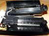
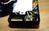
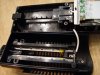
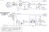
Looking for schematic to build Ionic Air Cleaner similar to sharper image Ionic Breeze Quadra Silent Air Purifier #SI637SNX [url]https://www.sharperimage.com/us/en/catalog/productview/sku=SI637SNX/hppos=1 [/url] As far as I know it uses high voltage transformer or more likely stepup voltage circuit connected to few metal plates so the dust stick to positive charged plates while air flows through them. Any ideas or maybe schematics ready to build would more then welcome here.

Video here: https://www.sharperimage.com/us/en/video/mediaSI637.jhtml
 
This an interesting one, I wouldn't mind finding out myself ;)

I've built a few Ionisers, but they all tended to be the standard needle type. The stainless steel plate method (probably patented) sounds ideal, no needles to erode and loose efficiency.

As to how they are getting the ion flow with plates is intriging, usually there needs to be a point for the streaming of the ions, I can understand the attraction of the dust etc sticking to the charged plates, I would have thought a fan would have been used, but I don't think theres has?

Maybe they are using partical acceleration, achieved by electrodes in a line, each being fed off different taps off the HT voltage?

As they mention Low-Ozone, I would assume the working voltage to be about 3 to 5kV.

I'll keep an eye out for this ;)

Steve
 
Using high voltage to clean the air is relatively common. Devices that had some pretty interesting names including "smoke-eater" used to be installed in bars and restaurants to get rid of smoke. A very common industrial air cleaning device uses the electrostatic principle (Trion is one company). Lots of home furnace air cleaners are electrostatic in nature as well. Thinking you might search thru some of this equipment for information. With all devices listed a fan is employed.

One thing to realize is that in most residential situations there is air movement at all times - very slight in some cases but it's there. I'd like to use a smoke gun or candle to see just how much breeze results from such a device.
 
I know for sure there no fan or any others moving mechanisms involved. It works dead silent and air flow very noticeable if you come close enough to the device (b.t.w. it smells very fresh too). Power consumption just about few dollars in a year if operated 24/7. All maintenance needs to be done is wipe dirt and dust from the metal plates once in a week or so.
 
I've ALSO been searching for a way to do this, because a couple hundred dollars for a unit seems outrageous. I suppose if you have the know-how to produce something that most common folks cannot readily reproduce, you can charge an arm and a leg.

I'm on the search as well. I'll let you know if I find anything substantial.
 
The negatively charged air particles get repelled by the negatively charged needle, as well as attracted to the positive side. That's where the breeze comes from. The fact that suspended particles are aggresively attracted to the positive plate is a bonus.

There's even a bunch of guys making "lifters", ultralight but pretty huge, that lift themselves up by that ion breeze effect. It looks like they've taken its effectiveness to new levels, but it'll never be able to lift its power source or even the HV DC/DC converters. Runs off of a tether that supplies its HV power. I did look it up at one point, there are studied parameters which say how much thrust is possible for power input. Wasn't extremely high, but neat.

Seach for "high voltage lifter". They have a lot of good homebuilt ion breeze info you'll be able to implement, since they take it pretty seriously.
**broken link removed**
 
8) Oznog... your the fella.. Very interesting reply, grabbing the lot now. We should be able to glean some info for the charge-plate from this info.

Had a good look at the data. As for the 'Plate' method, it would seem logical to reverse the arrangement to have the plates as positive, with some sort of vertical 'Negative' rod/wire nearer to the air-vent grill. The positive plates mounted horizontally (or maybe vertical?) with an air gap of whatever distance, to prevent arcing etc. Even though the negative rod is not a needle type point, the influence of the positive charged plate array should still cause an Ion flow towards the rod/wire, which should blow out the front grill. With a similar grill at the rear for the 'polluted' air input, we should have air-flow. The plates could be mounted horizontally to a vertical metal rod/tube, with gaps between the plates of unknown? spacing. For cleaning? I would imagine a quick-release mounting, that holds the rod and plates, also supplying the positive volts.

As for safety, isolation using micro switches etc, for the rear cover removal.

But I don't think the plate version will be using 25kV :shock: the Ozone released would be outside safety limits. I still think it will probably be in the area of 3 to 5kV.

I hope this invokes readers to refine any areas/mistakes mentioned the above, it maybe a starting point?

I fancy building one for my workshop, which gets dusty. Plus I smoke :oops:

Steve
 
Small version
 

Attachments

  • 3.jpg
    3.jpg
    90.4 KB · Views: 2,618
  • 2_167.jpg
    2_167.jpg
    64.4 KB · Views: 2,608
  • 1_646.jpg
    1_646.jpg
    99.1 KB · Views: 2,736
This one with variable output from 0 to 30KV should be more then enough to build large model but I think we don’t need such monster so schematic can be taken as sample to design something less powerful with lower voltage output.
 

Attachments

  • PS.JPG
    PS.JPG
    69.7 KB · Views: 4,043
Nice one ymmy.

So they are using 'Points' of sorts, to achieve some sort of air-flow. What isn't apparent is how the plates are removed, or whatever, for cleaning? as it all looks a bit tight in there. I assume these must 'slide-out'? for user cleaning? It looks like there's more than on 'Pos' collector plate?

When I'm free of work here, I'll post some (theoretical) drawings of how we maybe able to achieve it.

We appear to be getting closer ;)

Steve
 
Yes, plates slide in and out for cleaning purpose. Microswitch used to remove power once plates lifted up.
 

Attachments

  • 4.jpg
    4.jpg
    99.8 KB · Views: 2,440
  • 5.jpg
    5.jpg
    101.3 KB · Views: 2,474
  • SI.jpg
    SI.jpg
    33.6 KB · Views: 2,416
One more taken from internet...
-------------------------------------

1. Function
The basic part of this project is a resonant low-voltage DC powered voltage converter. A standard mains transformer is used backwards, i.e. supplying an alternating current into the low-voltage secondary coils and transforming this voltage level up to a high-frequency AC voltage which is then rectified in a three stage cascade multiplier.
The transformer used in my prototype is a 240V/2x12V, 1.5VA type printed circuit board transformer. The middlepoint of the two secondary windings is connected to the low-side supply voltage of 12V, while the other ends of the secondary coils are alternating connected to ground by two power MOSFETs. The gate voltage for the MOSFETs is directly derived from each two parallely coupled CMOS inverters by thus using only one chip for the oscillator and driver circuitry. The frequency is derived from an RC oscillator build by two CMOS Schmitt trigger inverters, a timing capacitor and a trimmable resistor for frequency adjustment.

--------------------------------------

2. Construction
The circuit of the high-voltage air ionizer consists of 3 parts
1. RC oscillator and power driver
2. high-voltage cascade multiplier
3. ion generator
I'm going to describe each of the parts in more detail now.

1. RC oscillator and power driver
The RC oscillator used here is quite simple and a very usable circuit. It uses two CMOS inverters with Schmitt trigger input characteristics (using "normal" inverters results in asymmetric square wave output with a duty cycle different from 50%). The oscillation frequency is determined by the RC time constant of the timing capacitor and resistor, using a variable resistor of up to 1MOhm and capacitors from 100pF up to several 10µF a wide range of freqeuncies can be covered. The output of the first and second inverter show a 180 degree phase shift and are fed into each two further inverters which are used as decoupling buffers driving the large gate capacity of the power MOSFETs (typically 1000pF). As the gate signals of the two power MOSFETs are in antiphase, always exactly one of them is in the conducting state driving current through one winding of the transformer.
The whole circuit shows a resonancy where the voltage on the high voltage side reaches a maximum. Using the given type of transformer and dimensions of the cascade, this frequency is approximately around 15kHz. As the MOSFETs are operated far below their critical values, no additional cooling is needed.

2. high-voltage cascade multiplier
On the high-voltage side of the transfomer, a high voltage is induced. Looking at the oscillogram of the drain voltages of the power MOSFETs you'll see, that even there a voltage significantly higher than the 12V supply voltage occurs due to self induction and cross induction from the other driven winding. Providing a large transient dI/dt on the low voltage side, the AC high voltage is higher than the perhaps expected 220V from the windings of the transformer...
The six capacitors and diodes in the three stage cascade work as a charge pump. By turning all diodes around in their direction the output of the cascade would be a positive DC voltage instead of negative as in the presented design. By exchanging the switching diodes with faster ones, the efficiency could increase. This part of the circuit should be build up with good isolation otherwise creeping currents will consume most of the generated power. Avoid sharp points on the circuit board and soldering points as these would give rise to an increased electrical field and possible leakage. The open circuit voltage in my setup is somewhere around 4kV, but even when probing with a 50MOhm impedance high voltage probe, the measured voltage decreases to about 2kV. From this the impedance of the cascade can be estimated to 50MOhm and the maximum output current to below 80µA

-----------------------------------------------

3. ion generator
What to do with the high voltage generated by the cascade? By generating a high field e.g. at a sharp point or wire end, a sensable wind of ions can be generated emerging from this pin point. The high-voltage potential can be adjusted by driving the circuit at a frequency slightly below or above the resonancy. Driving it under resonancy might actually give a too high voltage for the use as negative ion generator which will result in the production of some amounts of ozone (it smells a bit like chlorine and should be avoided). You can find the actual resonant frequency by monitoring the DC current going into the circuit from the 12V power supply. It peaks at the resonancy with a value of about 40mA depending on the transformer used.
An effective ion generator can be build by spreading the single leads in a multilead wire into the air and connecting the other end to the top point of the cascade. In a distance of about 1cm a guard ring connected to the ground level can be installed. Powering on the circuit you should be able to feel a faint wind coming from this assembly and in the dark you might see small blue lights at the ends of the wires.


Partlist
C1 470pF timing capacitor
C2-C7 4700pF/1600V ceramic high-voltage capacitors
C8 100nF
C9 100µ/25V
D1-D6 1N4007 or faster diodes Vbr>1000V
IC1 4584 hex Schmitt trigger inverter
Q1 BUZ11 Vds=50V, Id=30A, Ron=0.04Ohm
Q2 BUZ11 Vds=50V, Id=30A, Ron=0.04Ohm
R1 1M trimmable resistor
TR1 240V/2x12V, 0.75VA each standard PCB mounted type
 

Attachments

  • ionizer_sch.gif
    ionizer_sch.gif
    24.8 KB · Views: 5,200
Below is a GOOD Electrostatic Filter and a supply circuit. For an effective filter, the plates must be at least 4 inches deep or the amount of dust it collects will not be very efficient. A supply of over 5000 volts WILL PRODUCE HARMFUL OZONE.
 

Attachments

  • Electrostatic-Sch.jpg
    Electrostatic-Sch.jpg
    48.8 KB · Views: 3,153
  • Electrostatic.jpg
    Electrostatic.jpg
    55.7 KB · Views: 2,663
chemelec Wow, this is interesting one but I heard in order to achieve good ionic breeze the voltage should be around 10-15KV and now you talking about ozone problem...Where did you get schematic from?
 
Nice one chemelec :) The thin wires is a tidy way of arranging the negative electrodes, no machined spikes.

ymmy, 10-15KV may produce more 'breeze' but would punch out much Ozone, not healthy. All the info I've seen seems to suggest around 3KV to 4KV.

Steve
 
I Designed that circuit myself. It works very well.

That Pictured Filter I posted is out of a GOOD Commerical unit. And I have also built quite a few simular units.

There is some more info on this subject in the "Projects area" on my site at: **broken link removed**

Or I can answer questions if you e-mail me. You MUST put an Appropriate Subject line.

Take care..........Gary
 
Ymmy, If you want More Info on part values, E-mail me Direct.

1N4007 or 1N4008 or better yet, a High Voltage/High Frequency type.

Caps, .001 or .01 @ 1KV Minimum

1 meg, or even as low at 47 k rated at 1/2 watt, but MUST BE a "High Voltage Type Resistor. Most Standard Resistors are only rated at around 300 volts and will short out.

chemelec@hotmail.com

However, All E-mails Without the word "Electronic" in the "Subject Line" get Automatically Deleted.

So Make sure you put it in.

I have all these parts available if Needed.

Take care........Gary
 
chemelec thanks!
Now i can't find any reference for 2S0401a transistor. Wonder if part # correct or no?
 
Status
Not open for further replies.

Latest threads

Back
Top