Continue to Site

Welcome to our site!

Electro Tech is an online community (with over 170,000 members) who enjoy talking about and building electronic circuits, projects and gadgets. To participate you need to register. Registration is free. Click here to register now.

  • Welcome to our site! Electro Tech is an online community (with over 170,000 members) who enjoy talking about and building electronic circuits, projects and gadgets. To participate you need to register. Registration is free. Click here to register now.

Inputs

Status
Not open for further replies.

Scarr

Member
Hi,

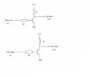
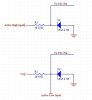
I want inputs that can be selected to be active high or low, these inputs can be between 12v-24v

I have attached my attempt at the two different input types and could just add jumpers to make it one circuit but I don't think this is the best way or is it?

Also, I'm concirned about what would happen if say 100v is applied to a input.

P.S. Trying to avoid using opto-isolators because of board space, unless you guys know of a to port SMT opto-isolator.

Thx
 

Attachments

  • input.jpg
    input.jpg
    32.5 KB · Views: 512
Scarr, I suspect that no one understands your question. Are you applying logic levels that go from a low of 0 volts to a high of 12 or 24 volts?

What do you mean by the statement "I want inputs that can be selected to be active high or low"? Unless I misunderstand your question, your software can make that selection.
 
It looks like this would help.
I'm assuming your imput (vout) is always active with "high" level.
The VCC value will of course depends on the Vout high level you want.
The resistors on the VCC R1 will depend on the current you need on your circuit imput (vout). If you have high impedance which requires vely low current to operate, like logic IC, the VCC resistor can be about 1K.
The base resistor Rb will depends on the transistor you use (HFE), VCC, R1 and the imput voltage Vin.
Like you said, if you apply 100V at Vin, you need to be sure to calculate Rb accordingly to avoid burnning the transistor by base-emitter over current.

Nilo
 

Attachments

  • Imput.JPG
    Imput.JPG
    13.1 KB · Views: 503
While I'm also somewhat confused by the question as well, it's quite simple to feed a PIC input from a higher voltage than it's normal logic supply. Simply feed the pin via a series resistor (like the one in the diagram), but use a higher value (you don't need a zener). The inputs on a PIC have protection diodes built-in, one to Vcc and one to Vdd, they will automatically clip the input to the required logic levels. All you need to do is pick the value of the series resistor high enough to limit the current to within the diodes ratings (given in the datasheet).
 
Sorry, I'll clarify

OK,

I have inputs from a vehicle, these can be either high (+12v-+24v)
like ignition etc. or configured as active low like a door switch going to ground. so need to be held high normally. I use +5v form my circuit to hold the input high in this active low configuration.

I also want these inputs to be able to withstand abuse, like spikes ect. and Ideally debounce. (but from my experiments this does not appear to be a problem. so if it complicates things forget the debounce)

You can see the two atempts I have done, any ideas?

P.S. Hope this clarifies it.
 
On either circuits I posted before, use VCC as 5VDC and R1 as 1KOhm. For the first one RB=100KOhm and for the second one RB=39KOhm.
It should be able to give you what you need for the imput of either 12 or 24VDC.
If boucing turns a problem, just split the RB into two resistors(Rb1=Rb2=Rb/2) and add a 100nf capacitos from its center to the ground.

Nilo
 
Status
Not open for further replies.

Latest threads

New Articles From Microcontroller Tips

Back
Top