MD MUBDIUL HASAN
Member
Hi there,
I am looking for a customized design where good power solution can be applicable.
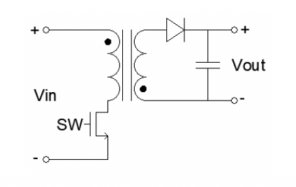
My aim is to develop a DC-DC sutable toloplogy ( flyback, buck, isolated ,..so on) converter with following parameter,
INPUT: 250 to 650 VDC
OUTPUT: 24V/5A , 5V/3A, 12V/2A
Take a look at the similar product, https://www.eaton.com/content/dam/e...verter-data-sheet-brochure-emob0008-en-us.pdf
https://www.bosch-mobility-solution...high-voltage-dc-dc-converter-generation-3evo/
I am looking for a customized design where good power solution can be applicable.
My aim is to develop a DC-DC sutable toloplogy ( flyback, buck, isolated ,..so on) converter with following parameter,
INPUT: 250 to 650 VDC
OUTPUT: 24V/5A , 5V/3A, 12V/2A
Take a look at the similar product, https://www.eaton.com/content/dam/e...verter-data-sheet-brochure-emob0008-en-us.pdf
https://www.bosch-mobility-solution...high-voltage-dc-dc-converter-generation-3evo/