Continue to Site

Welcome to our site!

Electro Tech is an online community (with over 170,000 members) who enjoy talking about and building electronic circuits, projects and gadgets. To participate you need to register. Registration is free. Click here to register now.

  • Welcome to our site! Electro Tech is an online community (with over 170,000 members) who enjoy talking about and building electronic circuits, projects and gadgets. To participate you need to register. Registration is free. Click here to register now.

LT3511 Isolated Flyback Converter

aiaie

New Member
I've built the ±70V isolated flyback converter circuit using the LT3511 IC, based on the application example provided in its datasheet. My goal is to use this power supply to drive a voltage-to-current converter that needs to source up to 2 mA into loads as high as 30 kΩ.

When I test the converter without any load, I only get about ±40V at the output. When I add a load, the voltage drops even further. I’m not sure what’s going wrong.

I simulated the circuit in LTspice, and it performs as expected. The measured voltages on the actual IC pins also closely match those in the simulation, so I’m having trouble pinpointing the issue.

How should I go about troubleshooting this? What could cause this kind of voltage drop, and how can I ensure that I get a stable ±70V output across the expected range of load conditions?
 

Attachments

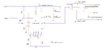
  • Flyback_Troubleshoot.PNG
    Flyback_Troubleshoot.PNG
    31.4 KB · Views: 66
U1 pin 1 is connected to the node between R1 and R2, as shown in the schematic in the original post. It’s offscreen in the image attached here.
 
Actually a bunch of waveforms will be helpful. Transformer pin 3 as well as the outputs to the diodes. It may be that you need one or more RC snubbers on windings.

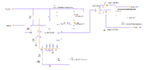
While we are discussing diodes, I think that the attached re-arrangement can give you better cross regulation. Note that I have added one more capacitor. This added capacitor bypasses leakage inductance between the two output windings. This should reduce the tendency of the more heavily loaded output voltage to sag lower than the more lightly loaded one. Another 470 nF might be enough in this added capacitor.
 

Attachments

  • Flyback_Troubleshoot_02.png
    Flyback_Troubleshoot_02.png
    37 KB · Views: 41
The schematic looks OK as does the layout. The only thing I question on the layout is: do you have ground flood on the unused parts of the top layer of the PCB? Also do you have a solid ground plane on the next layer down? This can often cause problems with high frequency circuits. If the schematic is OK and the transformer is not saturating (which it shouldn't) then the only thing left is the layout. You dont need a 600V ultra fast rectifier on the secondary and a lower voltage schottky will serve you better (rated at 200V reverse voltage). The output caps should not be breaking down, so the only thing left is the layout
 

Latest threads

Back
Top