Continue to Site

Welcome to our site!

Electro Tech is an online community (with over 170,000 members) who enjoy talking about and building electronic circuits, projects and gadgets. To participate you need to register. Registration is free. Click here to register now.

  • Welcome to our site! Electro Tech is an online community (with over 170,000 members) who enjoy talking about and building electronic circuits, projects and gadgets. To participate you need to register. Registration is free. Click here to register now.

Induction Heater Works but Bridge Rectifier burnes up in 3 minutes.

Status
Not open for further replies.

gary350

Well-Known Member
I built his induction heater and it works ok but not great. The circuit is rated 25 amps. The Mosfets are rated 35 amps. The bridge rectifier is rated 50 amps. It takes 3 minutes to over heat the rectifier and burn it up.

I tried several current blocking capacitors in series with the choke coil and the circuit will not work at all.

I tried a .75 ohm current limiting resistor in series with power supply the rectifier does not over heat but the circuit does not work well enough to heat a #18 steel wire red hot. I tried a .6 ohm current limiting now the bridge rectifier is getting hot again.

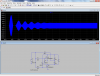
The circuits calls for a 2mh choke, I just happen to have one from a TV. This choke has 2 windings #16 wire 1mh each in parallel and my meter says it is 2 mh. The circuit calls for a 1" diameter 8 turns 1uh induction coil with a .47uf capacitor, I changed it to 4 turns with TWO .47uh, frequency is the same about 200KHz.

The transformer seconday open circuit voltage is 10.8 volts in my digital meter and 15.3VDC after the rectifier. When the circuit is on my meter reads 16.8 VDC at the power supply. The transformer is capable of producing 100 amps.

**broken link removed**

**broken link removed**

**broken link removed**
 
Last edited:
Then you probably need a much bigger heatsink. Try measuring the temperature of the rectifier and calculating the junction temperature.
 
Then you probably need a much bigger heatsink. Try measuring the temperature of the rectifier and calculating the junction temperature.

The rectifier heats up faster inside than it does outside. It gets hotter on the bottom side than the top side where the heat sink is. It pops then a bunch of black smoke comes out. The bottom side is too hot to touch but the side and top are just starting to get hot. 2 minutes later the heat has had time to transfer to the heat sink then it is too hot to touch.

I found on line a warning about these bridge rectifiers. Even though they are rated 50 amps they are only good for 15 amps. 2 rectifiers in parallel are good for 30 amps. It appare to to me I need to put 3 or 4 rectifiers in parallel to make sure they never over heat. I also learned LUTZ wire works best for high frequency because of skin effect. I also learned a lower frequency of 60KHz is better than 200KHz. Also the claim that several caps in parallel work better than 1 cap is not true. Also a larger metal part in the coil produces more inductance and pulls less current.
 
Last edited:
At such high currents , one has to use low drop rectifiers. imagine with the half cycle where two diodes are involved would tend to drop 1V at each . at 25 amps current, the power dissipated is expected to be 25watts or higher as load is inductive. divided by power factor. hence the power waste could well be 25/0.8
I propose to use schottky diodes bridge.some designs use even power mosfets as bridge as they have least drop.
 
Yeah, at those currents I'd probably go individual or at a push dual to220's (or similar) shottky rectifier diodes. Then you can work out the proper heat sinking you need on them, and there are plenty available heat sinks for them.
 
The circuit is rated 25 amps. The mosfets are rated 35 amps. The 50 amp rectifier should be large enough but it is not.
That rating is probably only with a big heatsink.
Yours is kind of small.
 
I would say that your bridge rectifier is grossly over rated and under heatsinked.

I have built a number of higher powered 12 volt DC power supplies over the years that I used the same style of bridge rectifiers in and they have had no problems feeding 30 - 40 amps continuous loads even with around 100,00 - 150,000 uF in capacitors behind them for hours at a time but they have heat sinks about 20x the size you are using.
 
^^^How you doing tcm?
Great to see you helping and advising again :)

All the best,
tv
 
The bridge rectifier over heats and burns up before the aluminum case of the rectifier has time to get hot. About 2 minutes after it has burned up the aluminum case is too hot to touch. Heat sink is doing nothing if the aluminum case will not heat up faster.

Today I am going to connect 5 bridge rectifiers in parallel on a very large alumunum heat sink. 5 in parallel will lower the resistance and this power supply will be good for a higher power project.

Can I put several Mosfets in parallel to get more power to the induction coil ???
 
Today I am going to connect 5 bridge rectifiers in parallel on a very large alumunum heat sink. 5 in parallel will lower the resistance and this power supply will be good for a higher power project.

Bad idea gary350. You have stuff going on there that nobody can really help with. Because we are not sitting next to you and therefore cannot accurately guide. I say leave all alone for now.

Tomorrow is another Year:)

Stay safe

Regards,
tv
 
Power supply is working fine I tested it without the induction heater attached voltate is up 3 volts to 19.62 VDC. Load voltage is 12.4 volts and constantly dropping.

With the induction heater circuit board attached I have a NEW problem. Mosfet tempeature climbs to 130 degrees in 20 seconds so I shut it OFF. Mosfets heated up so quick I'm not sure a larger heat sink is the answer.

Maybe I need some current limiting.

**broken link removed**

**broken link removed**
 
Last edited:
WOW...solder selection of note.

All the rolls. Very impressive. Leave it alone. Still.

Regards,
tv
 
Circuit drawing calls for 2mh choke coil. I changed it to 4mh it helped a little, mosfets over heated in 30 seconds instead of 20 seconds.
 
Last edited:

Attachments

  • ind.png
    ind.png
    92.4 KB · Views: 236
Last edited:
I know what is wrong, I have the wrong circuit drawing. The wrong circuit drawing is all over the internet it shows 15v at the gate and 15v at the source. I finally found the correct drawing it shows a 12v regulator on the gate.

I can order a 7812 voltage regulator and wait another month for it to arrive or maybe I can build a voltage divider at the power supply. I will need a circuit drawing for the voltage regulator? The Mosfets tutorial says the gate needs very low current. So if I put a 3k and 12k resistors in series across the 15v power supply I should have 12v at 1ma across the 12k resistor. The only resistors i have are 1/4 watts, 15k x 1ma = .015 watts. Will a voltage divider work to get 12 volts for the mosfet gate???
 
Last edited:
If ever it doesn't start oscillating the current will be really high. Do you have a scope?
It looks like you only have 4 turns and 1 ufd cap. When I simulate it, it runs pretty fast (250Khz)and has a little trouble starting. I use this calculator to calculate the inductance.
https://www.daycounter.com/Calculators/Air-Core-Inductor-Calculator.phtml

As far as I can see "Ron" he's got 8 turns as to the cap? You must have better eye's than I do; or did I have to many "Lemon Tequila Shots" with the wife last night. When I Zoom in I'm seeing a 3300uF at 50v?

By the way,

Happy New Year, Ron.

kv:)

Edit: I think I see the "4" turns after the "8" turn center tap in the schematic.
 
Last edited:
As far as I can see "Ron" he's got 8 turns as to the cap? You must have better eye's than I do; or did I have to many "Lemon Tequila Shots" with the wife last night. When I Zoom in I'm seeing a 3300uF at 50v?

By the way,

Happy New Year, Ron.

kv:)

Edit: I think I see the "4" turns after the "8" turn center tap in the schematic.

The person that original built this circuit used 8 turns for the induction coil then in a later project he used 4 turns and doubled the capacitors to keep the same about 220KHz frequency.

There is another guy that built this project he shows the original circuit with no voltage regulator like several other people have done. He experemented with different induction coil frequencies and says, 60KHz works better than 200KHz. He shows the circuit with no 12v regulator.

None of the other 6 or 7 projects online say anything about a 12v regulator but 1 guy mentions he used a 12v regulator, but talks like it was his idea and sounds like it is a improvement over the original circuit.

The first guy later on after several other projects finally mentions the 12v regulator is needed.

After reading the tutorial on Mosfets i realize the 12v regulator really is needed. The circuit drawing does not show the 12v regulator so I had no clue it was needed. I have several voltage regulators pulled from old TVs, most or 5v i might have one that is 10v. It will take a month to get a 12v regulator from china. I use to get things from china in 7 to 10 days but not anymore. I might experement with a voltage divider on the power supply later today and test it with the meter before connecting it to the induction heater circuit.

Here is my new circuit tell me what you thing?

**broken link removed**
 
Last edited:
Status
Not open for further replies.

Latest threads

New Articles From Microcontroller Tips

Back
Top