Roff - Thanks for the explanation. So, If i understand correctly, if there is a load on the circuit that pulls the voltage slightly lower than Vs, the HE sensor output per magnetic input will change, but the LM331 frequency will not, so I cannot guarantee that the change in frequency observed at the LM331 output is truly due to magnetic influence on the HE, it could be just voltage fluctuations on the Vs to the HE.
Eric - thanks for taking the time to replicate the circuit and confirm the findings..
Mr Al, I did some testing last night prior to reading your post (so I was using my original circuit) but I think I have covered the bases you wanted me to. Also, I mis-stated my supply specs. The circuit is currently powered by a phone charger wall wart, rated output 4.8volts, 750 ma.
I reconstructed the circuit in stages and took voltage readings as I went along.
First off, the correction on the supply, it's a 4.8v, 750 ma rated supply. A quick check indicated that
(1) No load voltage = 4.81v
(2) 22 ohm load (target 218 ma), voltage drops to 4.74v
(3) 10 ohm load (target 481 ma), voltage drops to 4.63v
So probably not a regulated supply.
Onwards...
(1) Vs = 4.81v
(2) HE no magnetic field and not connected to the circuit = 2.40v
(3) HE with example signal (weak magnetic field) and not connected to the circuit = 2.42v
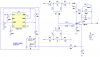
Connect Hall Sensor to LM358 in- through 10K. (feedback to in- not connected). Voltage divider (22K plus 50K POT) connected to in+ (Vref)
(4) With Vref = 2.40v, Vout (from LM358) = 3.50v
(5) With Vref = 4.80v (max Vref I can produce), Vout = 3.50v
(6) With Vref = 1.40v (min Vref I can produce), Vout = 0.00v
(7) Set Vref to 2.36v, Vout = 0.00v
(8) Set Vref to 2.41v, Vout = 3.50v (these last two (7 and 8) were to get me close to the switching point)
(9) With Vref at 2.41v and Vout at 3.50, application of weak HE signal (representing an increase from 2.40 to 2.42v at the in-) the signal dropped to 0.00v
Connect LM358 output to in- without Rf - circuit becomes insensitive to the HE signal. Vout moves from 3.46 to 1.42v as the Vref is set at 4.81v and 1.42v respectively. Setting the Vref to 2.38 makes the output go to 2.4v but the circuit does not respond to the signal from the HE.
Added 10K Rf from LM358 output back to in-.
(10) Vref at 2.38, Vout at 2.4, apply HE signal, Vout drops to 2.38
(11) Adjust Vref to min and max (1.4 and 4.8v), Vout moves from 0.62 to 3.48v
(12) adjust Vref to 2.8v, Vout is 3.24v, apply HE signal and Vout drops to 3.22v
So with the 10K (1x amplification) connected, the output is shifting by the correct magnitude and in the correct direction when I apply a field to the HE
I realized at this stage that I was using the opposite polarity field to what I had been using previously (HE signal is going up by 0.02v with application of field because the magnetic polarity is different to what I was using earlier)
So I switched the field polarity and repeated point (12) above
(13) Vref at 2.8v, Vout is 3.24v, apply HE signal, Vout rises to 3.26v
(14) Set Vref to 1.53, Vout is 0.70v (close to the minimum of 0.62v), apply HE signal, Vout rises to 0.72v
So the circuit responds predictably to the different HE signal (inverts by the same magnitude).
I shorted in+ to ground, Vout became 0.62v, HE (with no signal) still outputs 2.4v, circuit non-responsive to HE when magnetic field applied (no surprise there).
Removed short to ground and confirmed that circuit is behaving as in (14) above
(15) Vref = 1.53, Vout is 0.70v , apply HE signal, Vout rises to 0.72v
Added positive voltage injection through 10K to in- as suggested by Mr Al
(16) Vout dropped from 0.70v (in 15) to 0.66v with addition of positive voltage injection
(17) Adjust Vref until Vout returns to 0.70v (Vref now = 2.61v), apply HE signal, Vout rises to 0.72v
So the Voltage injection works in that the circuit is still responsive to the HE signal, however, the circuit will still not adjust to 0.00v output (or close to). The positive voltage injection actually increased the lowest level I can go to from 0.62v to 0.66v.
DamoRC

")
")