Continue to Site

Welcome to our site!

Electro Tech is an online community (with over 170,000 members) who enjoy talking about and building electronic circuits, projects and gadgets. To participate you need to register. Registration is free. Click here to register now.

  • Welcome to our site! Electro Tech is an online community (with over 170,000 members) who enjoy talking about and building electronic circuits, projects and gadgets. To participate you need to register. Registration is free. Click here to register now.

How to reset this ic without any switch....

Status
Not open for further replies.
Hello alec.... I have read your post and I have also discuss with my friend and he replied to me :
=================================================================
You have had a great deal of difficulty attempting to build my tried and tested circuits.

You are now proposing to build a circuit that has never been built before

So far - the best that can be said is that the circuit works in a simulator.

That doesn't mean it will work in reality.


If you build the entire circuit at once - and find that it doesn't work -

You won't know where the fault/faults lie.

And your lack of experience will make it difficult for you to sort the problems out.


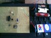
The circuit will have to be built and tested,

That much is true.

I have been trying to encourage you to approach this task in stages.

And check its performance as you go.
===================================================================

As he said we should make this circuit in stages because Alec I dont have good electronics knowledge so minor fault can damage the IC several times...

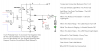
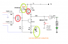
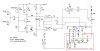
So Ron said and he given me the the circuit diagram so that I can complete your full circuit by stages..... easily and conveniently....

so alec what do you say ??? :)
 

Attachments

  • Part One.png
    Part One.png
    12.1 KB · Views: 156
I agree it's a good idea to build this in stages, and your friend's circuit is a good stage 1.
(1) Re the beeper connection, we don't know which (if any) beeper terminal is connected to which clock battery terminal. To play safe, simply connect one beeper terminal to the stage 1 circuit ground and connect the other beeper terminal to the 'Clock 1' terminal. I am assuming the clock has its own separate battery.
(2) My design calls for the R3 trimpot to be set so that pin 1 of the gate U1a goes to about 2/3 of +V at power-up and stays there until a beeper signal is received. The operation of this stage will not then be as your friend suggests. So the comments in the right-hand column of the picture in post #81 should instead read as follows :-

Temporary connection between pins 1 and 2 of U1.
The LED should be OFF when you power up.
When you push the button the LED should turn ON.
When you release the button it should go OFF again.
When/while the alarm rings the LED should flicker or dim.
When the alarm stops the LED should go OFF.
It should do this reliably every time. Start with one clock
connected then check it still works with both clocks connected.
 
OK alec ..... thanks .... I am going out of station for buying some electronic ic and components for this project... As I stay in village so here I dont get any ic or electronic components ... so I am going out of station far -away from my house to buy electronics ic and components to complete this project..... So as I return I will make it and If any problem occur I will let you know... Ok...

by the way thanks for your help ... and sorry for late reply as my internet connection was temporary down.....

and.............

and friend Is there equivalent transistor in place of 2N2222.. please give some transistors numbers so That while buying I will get these also... because I cant go every time as it is very far from my house It cost lots of money... so please define any equivalent transistors of 2N2222..
SO that...If this transistor(2N2222) is not available then I can purchase another transistor which will work with my circuit...
 
Last edited:
Almost any low power general-purpose NPN transistor will be ok instead of the 2N2222, e.g. BC184, BC337, BC547, 2N2219, 2N3704, 2N3904.
 
HELLO ALEC ...

I AM BACK...I HAVE BOUGHT THE COMPONENTS BUT SOME COMPONENTS ARE NO AVAILABLE.... BUT ALMOST ALL I HAVE GOT......

HERE I HAVE ATTACH THE CIRCUIT DIAGRAM............
THE COMPONENTS WHICH ARE NOT AVAILABLE IS MARKED IN RED IN THE CIRCUIT DIAGRAM

C1 & C2..

I DIDN'T GET ANY IF THE ABOVE CERAMIC CAPACITORS..
I ONLY HAVE :
---> 10NF (CERAMIC, WHICH ARE SMALL AND YELLOW IN COLOR) AND CODE IS 103...
---> 100 nf AND THE CODE IS 104...
---> 3.3 nf AND THE CODE IS 332...

`````````````````````

AND THE COMPONENTS WHICH ARE MARKED IN GREEN SHOWS CAN I REPLACE IT... WITH THE VALUE SHOWN..

R3 & C3...
``````````````````````````
R3 : 500K TRIM POT
C3 : 1UF ELECTROLYTIC CAPACITOR....
````````````````````````````````````````


THANKS IN ADVANCE...

KINDLY ACKNOWLEDGE :
YUSUF
 

Attachments

  • Part_One.png
    Part_One.png
    19.2 KB · Views: 171
Try the 10nF (first choice) or 100nF (second choice) for C1, the 3.3nF for C2. These alternatives will affect the frequency response of the amplifier so it may not be as effective as intended. You will just have to hope it's ok with your particular beeper signals.
The 500k trimpot will suffice for R3.
C3 is specified as 1uF; which is what you have?
 
Last edited:
hello alec.....
i have tried making this circuit but after creating it ... when i powered ...

it doesn't worked .... I was not getting any response by pressing switch or adding alarm clock circuit.... the led was off and it remained off...

.... and also battery and ic was heating .......

i looked all the connections very well and my all connections was perfect.........

i have attach my circuit which i have made.......

So what should I do..... forward..
and one more thing , I have replace the switch with small wires....... so while touching the wires it will work as switch....

so alec.... kindly help... what should i do forward....

thanks...
 

Attachments

  • Image003.jpg
    Image003.jpg
    419.6 KB · Views: 165
.... and also battery and ic was heating ....... i looked all the connections very well and my all connections was perfect.....
Clearly all the connections are NOT perfect. Let's hope the components survived being heated.
Make doubly sure that you have correctly identified which way round the IC is connected, and that its ground (Vss) and +V (Vdd) pins are of the correct polarity and connect only where they should. Check also that there are no solder blobs or bare wires shorting out connection points. BTW, you should have followed the advice above and first of all built just the amplifier part (i.e. without the counter IC shown in the picture).
I'm afraid the picture (even if it were sharp) gives no clues as to how the components are interconnected and where the problem might lie.
The battery will obviously have to be replaced by another power source when you get the circuit working and are driving a relay with it.
 
Ok alec.... I am looking again. my circuit...... and I am only making amplifier part..... friend


and If i remove the alarm clock circuit and only press swith then will the led glow.....

just for only testing...
 
Last edited:
wow........ great alec.......... you are brilliant....

I have checked the connections as you have said ... and the problem was lying in the vss and vdd... I have connected incorrectly ... now I have connected correctly and the result was as follows....

when I press switch ( the two wires) the led glows....

but as i connect my alarm clock circuit the led doesn't glow... and also while touching the the tips of the terminals in this circuit (where the alarm clock beeper pulse is connected) the led glow......

I hope .. this means that amplifier is working and while getting the pulse from the alarm clock the led doesn't glow or blinks...

help......
 
That sounds more promising. The stray electrical signals present at your fingers are probably much higher voltage than your beeper signals, so that is why the LED glows. You now need to adjust the amp bias to suit the beeper signals. As you are using a 9V battery you need to adjust the pot so that the voltage at the connection point between R5 and the Q1 collector is about 6V with respect to ground. The LED should then be off if there is no beeper signal but glow in sympathy with the beeper signal.

Edit: The beeper has two terminals. Do you have two wires connected from there to the amplifier input?
 
Last edited:
Hello alec ... again ... I have done as you said and the result was :

Yaa I have 9V battery but it is little old so it's voltage is : 8.49
and I had powered the circuit and first I have put the multimeter black (-) probe in ground and the red(+) probe on in between R5 and the Q1 collector.... and I took a screw driver and put it into the pot and start rotating until the voltage reached 6V. but as I remove the screw driver from the pot the voltage changes and comes on it previous position.. as i touch the with screw driver again the voltages goes to 6V... and also while touching the amplifier input positive terminals with finger the voltage comes to 6v and while leaving the the voltage comes to previous state...

and...........

the led is remained off....... and it was not working with alarm clock circuit.... so I added the beeper in the alarm clock circuit where it was placed and as the beeper begins to rang the led also glows sympathy with the beeper signal... and as the alarm stops the led also becomes off.... but by removing beeper or without beeper and only connecting two wires of the beeper to the amplifier input it doesn't work.... the led remained off..... forever...

and While making this project my mobile was near the circuit as the call came on my mobile the led started to blink with mobile... but as i moved my mobile little bit far the led stops blinking ...... but as I took my mobile near the led the led started to blinks.. but the led blinks only if call comes or goes from mobile else it stays off...

thanks.. :)
 
Last edited:
Hello alec ... again ... I have done as you said and the result was :

Yaa I have 9V battery but it is little old so it's voltage is : 8.49
and I had powered the circuit and first I have put the multimeter black (-) probe in ground and the red(+) probe on in between R5 and the Q1 collector.... and I took a screw driver and put it into the pot and start rotating until the voltage reached 6V. but as I remove the screw driver from the pot the voltage changes and comes on it previous position.. as i touch the with screw driver again the voltages goes to 6V... and also while touching the amplifier input positive terminals with finger the voltage comes to 6v and while leaving the the voltage comes to previous state...

and...........

the led is remained off....... and it was not working with alarm clock circuit.... so I added the beeper in the alarm clock circuit where it was placed and as the beeper begins to rang the led also glows sympathy with the beeper signal... and as the alarm stops the led also becomes off.... but by removing beeper or without beeper and only connecting two wires of the beeper to the amplifier input it doesn't work.... the led remained off..... forever...

and While making this project my mobile was near the circuit as the call came on my mobile the led started to blink with mobile... but as i moved my mobile little bit far the led stops blinking ...... but as took my mobile near the led the led started to blinks.. but the led blinks only if call comes from mobile else it stays off...

thanks.. :)
 
I haven't fully understood all that, but "so I added the beeper in the alarm clock circuit where it was placed and as the beeper begins to rang the led also glows sympathy with the beeper signal... and as the alarm stops the led also becomes off.." seems to indicate that the amp is now biased correctly. Progress!
I am not surprised a nearby mobile will cause the LED to blink. The amp, and especially its input wires, should be as compact as possible and properly screened, to prevent spurious signal pick-up. The amp was designed to be sensitive because you have not given us any values for the output signal level of the beeper. If the gain proves to be too high it can always be reduced by reducing the value of R5 and introducing emitter degeneration.
The next step is to mount the circuit in a screened box, with the beeper connected by a short screened wire to the circuit, then, with your fingers well away from the amp, confirm that the beeper sounding makes the LED glow. If that's ok you can build and test the rest of the timer.
 
Hi... Alec...

I have made all complete circuit with amplifier stage and timer as per your circuit diagram...

But I have not remade the timer which you have mentioned in your circuit diagram because as I have created this timer before so I have used that one....

and the complete circuit diagram with my timer is attach in my attachment..

I have just connected this amplifier circuit with the timer as same as in circuit diagram(Which you have given recently)....

Please have a look and suggest the working of this circuit...........

By the way I have tested this complete circuit and the result was :

I have replaced relay with led for just testing...

First I power my circuit....
After powering the led's on the both circuit remains off....
As the alarm clock begins to beep the Relay led glows.
and on another side the timer circuit also starts to run... with led indications..

But as my alarm clock beeper stops the timer circuit keeps on running till the preset time..
and the Relay led also remains lit.

and again after a while the alarm starts to beep but now the timer circuit doesn't reset.. it's led remains lit as it have been completed it's preset time....
and with it the Relay led also remains lit....


so please kindly acknowledge :
thanks.....................
 

Attachments

  • revised.jpg
    revised.jpg
    91.5 KB · Views: 140
Last edited:
HI... ALEC...

I am waiting with my circuit in hand for your reply...
 
You haven't built the circuit I gave you in post #78. That is why you are getting weird results.
 
friend............ I love you.................. thanks a lot............... I have made it....

:)
 
Ok alec.... Now it's time to build power supply ... for this circuit.. and say bye to battery..

as this circuit also contains relay .... then we should have 12 volt 100 ma current power supply.
I have a transformer-less power supply attached in my attachment ...

please have a look and reply alec...

thanks--
 

Attachments

  • Transformerless-power-supply-550x318.png
    Transformerless-power-supply-550x318.png
    17 KB · Views: 167
Aaarrrrgggghhhhh !! On no account build that transformerless supply: it's potentially lethal !!:eek:

Use a wall-wart instead. Is 12V 100mA the coil rating of the relay you intend to use?
 
Last edited:
Status
Not open for further replies.

New Articles From Microcontroller Tips

Back
Top