Continue to Site

Welcome to our site!

Electro Tech is an online community (with over 170,000 members) who enjoy talking about and building electronic circuits, projects and gadgets. To participate you need to register. Registration is free. Click here to register now.

  • Welcome to our site! Electro Tech is an online community (with over 170,000 members) who enjoy talking about and building electronic circuits, projects and gadgets. To participate you need to register. Registration is free. Click here to register now.

How to reset this ic without any switch....

Status
Not open for further replies.
I have replace led in place of relay... as per you told.
Actually, that's not what I told you. But your added LED plus resistor will be ok; so will the 500k pot.
As an indication that the timer is working, the R2 LED, driven by pin 9 of the CD4060, flashes at a rate ~ 137/T, where the rate is flashes per minute and T is the period in hours. [The R1 LED flashes at 1/16 that rate].
See the LED attached to R2? If the time period T is, for example, 2 hrs it will flash at 137/2 = 68 flashes per minute. And the LED attached to R1 will flash at that rate divided by 16, in other words 68/16 = ~4 flashes per minute. If you've changed C3 as discussed, for test purposes, your timed period T will be much shorter than 2 hrs. So if e.g. T = 6 minutes (0.1 hrs) the R2 LED will flash at 137/0.1 = 1370 per minute = 23 per sec and the R1 LED will flash at 1370/16 = 86 per minute.
 
Ok.. Friend i will try and if any problem occur i will let you know.. By the way thank you very much..
 
Hi.... alec.... :)

Well ,By distroying amost 10 to 12 ic's I have successfully made the timer....
Thank you my friend very.............. much... for helping me.... I love you........ :)

Friend I have made this 3 hr timer .... Now the next work is to attach this timer to alarm clock.... well you have send me the complete circuit... by the way friend just for learning I have dont some test... please innsure whether it is right or wrong....

Friend I had connected my beeper terminals to reset pin of IC as you can see the circuit in my attachments..
I have done like this just for learning ... I dont know what will be the result by doing like this ..so for learning purpose I have done...
And the results was , first I had started my 3hr timer then I touched the two terminals of my beeper into the reset pins as you can see in my images.... the timer green ,yellow led went off.. the timer became off... It remained off untill I take off my beeper wires from reset pins..... as I removed my beeper wires then the timer begans to run and continued.... so this was ok !!! I thought that If my beeper rangs then It continuely supply voltage to the reset pins untill the beeper becomes off.... so I have done second testing again,,,

but now my beeper was off it was not ringing........ I have start the timer then I again connect my beeper wires to reset terminals but the result was same as above.... I didn't understand why it was working like that....

The beeper was on ... the timer circuit was turn off untill the beeper becomes off but the beeper finish sounding but now also the timer circuit was off.. untill I physically removed the wires from reset pins..... as I removed the wires the timer starts to run...

So friend I doesn't understand why I got this result.......

I again removed my alarm clock cell and touched the beeper terminals wires to reset pins ... the timer turned off again and it remained off untill I removed the wire physically.....

so kindly help......
 

Attachments

  • reset.gif
    reset.gif
    18.2 KB · Views: 201
Last edited:
By distroying amost 10 to 12 ic's I have successfully made the timer..
A noble sacrifice, but can you tell us how they were destroyed?
If my beeper rangs then It continuely supply voltage to the reset pins untill the beeper becomes off.
That will continuously reset the timer. So the timed period won't start until either the beeper stops or it's disconnected from the reset pin. That is why the logic gates were used to make a set-reset latch in my suggested circuit; so that beeper pulses after the first one would be ignored and not cause multiple resets.
BTW, if you're handling wires while you connect/disconnect the beeper remember that the circuit is static-sensitive and could be damaged. Also, your body acts like an aerial and picks up all sorts of interference which may be getting through to the circuit and causing weird results.
 
Last edited:
when my beeper stops or I remove my alarm clock cells then also my timer doesn't start to run.... untill I disconnect my wires from reset pins.
That's probably because the internal impedance of the beeper circuit bridging the reset switch is keeping the timer in the reset state. That shouldn't happen if you build the complete circuit I suggested and connect the beeper to the input of the transistor amplifying stage as per the circuit. If you don't follow the designed circuit then (a) you shouldn't be surprised if you don't get the expected results and (b) it makes it difficult to diagnose any problem.

BTW the 'timer circuit' shown in your pic has only one chip (it looks as though you have added the label 'CD4093' to it), so it clearly isn't the whole timer circuit we are discussing.
 
Last edited:
Sorry if this is off topic but friend Alec you have my vote for being the most patient person!

Mike
 
Sorry.. It's was mistyping..The label is CD4060 not CD4093. Friend first i had made only 3hr timer circuit. I am making every circuit seperately on breadboard. So next i am going to make auto-reset circuit which you have given me the circuit diagram.. On another breadboard... So if any problems occur i will let you know my friend..
Thanks.. :)
I have very good trust on you.. But about this circuit diagram , one of my friend said :
The logic of the latch looks fine - except that the state of pin 11 at power-up looks random.
Pins 8 & 12 will be high -and pin 11 will be low if pin 10 takes pin 13 high,
But pin 10 could just as easily take pin 13 low -
In which case - pin 11 will power-up high.
You've also left out C2 from the 4060 circuit -
So at power-up - the 4060 will not get its reset pulse -
And it may not start itscount at zero.
As you have the circuit -the 4093 will not unlatchuntil both pins 2 & 3 of the 4060 are high
And that will occur after45 + 90 = 2h 15m
That's when pin 4 of the 4093 will go low.
However - doesn't matter when the 4093 latch is unlatched -
As long as it's unlatchedat some stage BEFORE the next clock input starts.
So the same output (3hrs) that de-energizesthe relay - and stops the count -
Can be used to unlatch the 4093 output.
BUT AT THIS STAGE - NONE OF THE ABOVE MATTERS.
What you need to knownow - is whether or not the 4093 actually produces a high pin 11-
When the alarms sounds.
If it does - you can worry about how best to use that high to reset the 4060 timer.
If it doesn't - you'll haveto look elsewhere in the circuit for a solution...
 
The points your friend makes are perfectly valid. Both the 4093 latch and the 4060 counter may start up in an unknown state when the existing circuit is powered up for the very first time. But does that matter? This circuit is going to be used 24/7, so will normally be kept powered.
Pressing the reset button immediately after that first power-up will resolve any uncertainty, but if you wish you can add automatic reset at power-up by adding C4 and C5 as in the attached revised circuit.
 

Attachments

  • Reset6z.gif
    Reset6z.gif
    29.4 KB · Views: 203
@lilimike
Thanks. I try my best!:)
 
Friend thanks..but I want to clear something because I have forget to say at beginning.......

Friend In India the electricity is not available 24/7... here electricity goes any time and comes anytime... it is rare that it stays 24/7 ...

So , will this circuit will work reliably ........
Sorry because friend I know this was very important to say at beginning but I was forgotten...

As it receives clock pulse then only the timer should run .. else it will not run....

And as in india the electricity doesn't have any fixed time to come.... so It can be possible that this circuit will need to power up more times as it depends on electricity.... so
I want that as the powering the timer(as many times) circuit it should not start to run until it gets the pulse from the clock......

so kindly have a look friend...
_yusuf
 
Last edited:
To prevent re-triggering of the timer at each mains power-up you will need to power the circuit, except for those components shown in red, from a battery (e.g. 4 AA alkaline cells). Those red-coloured components will have to have a separate, mains-derived, DC power supply of a voltage suited to the operating voltage of your relay. If that voltage is greater than the battery voltage the circuit will need modifying.
 
Thanks for your reply....

Friend, I have shown your reply to my friend and he replied :

"================================================================================
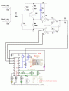
The revised circuit will power-up with pin 11 of the 4093 high - and the 4060 reset.

But that is not necessarily the best outcome.


Even in areas where the mains supply is reliable - there are occasional outages.

And the briefest of interruption in supply - will invoke the power-up response.

A non-technical end user - may not be present -
May not know there has been an outage -
May not know/recall that anything is required of him - etc.


What happens at power-up always matters.

You need to know exactly how the circuit will behave when power returns -

And you need to be certain that that's how you want it to behave.


If the alarm is ringing when the power returns - you want the 4060 timer to start

And if the alarm is NOT ringing when the power returns -

You want the 4060 timer to wait until the alarm does ring.

This is true - whether you have one outage a day - or one a year.

The reliability - or otherwise - of the mains supply is not important.


It should be possible to achieve the desired results

By making the correct connections between the the latch - and the 4060 timer.


But as I said.....

AT THIS STAGE - NONE OF THIS MATTERS.

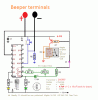
What you need to know now - is whether or not the 4093 actually produces a
high pin 11- when the alarms sounds.

If it does - you can worry about how best to use that high to control the 4060

If it doesn't - you'll have to look elsewhere for a solution.
"====================================================================================

Alec , This is the message my friend replied so I thought that I can share this with you... Because I dont have enough knowledge of
electronics so I also asked my friend...........

So Alec, what do you say about this....
Thanks :)
 
Your friend presumably hasn't seen the post #73 suggestion to power the circuit from a battery.

(1) What do you want the timer circuit to do if the mains fails during the timed period? Should it re-start? Or carry on from where it left off? Or stop altogether and give a warning indication?
It should be possible to achieve the desired results by making the correct connections between the the latch - and the 4060 timer.
(2) Ask your friend what connection modifications he would make to achieve those results.
 
Last edited:
OK alec... I will ask him what connection modifications he would make to achieve those results. ...
By the way thanks...

Alec... as you said....
(1) What do you want the timer circuit to do if the mains fails during the timed period? Should it re-start? Or carry on from where it left off? Or stop altogether and give a warning indication?

Friend the answer to this question is : I want that it stop altogether and give a warning indication... because main power is not available so there is not use of running... the only alarm clock will keep on running 24/7 because it is necessary to trigger at fixed time... and if the main power is not available it will be turn off... and as the main power comes and if this circuit receives pulse from alarm clock then it will start to run.... timer....

But friend please you suggest what will be the best solutions to this problem..... because I have very high trust on you.....
and friend I dont have good knowledge so that I can tackle this fault.......
So plsssssssssss help... and I am also requesting solution from my friend.... ..
Thanks :)
 
Last edited:
Hello Alec....

Today I showed your #73 post to my friend and he replied :

===================================================================

I am confident that preventing the timer from re-triggering at power-up is not a problem -

And it doesn't require batteries.

It just needs the right connections between the 4093 latch - and the 4060 timer.

But there's no point in going into those connections in detail -

Until you're certain that your clocks can actually trigger the latch.

Show me that your clocks will produce a high at pin 11 (light the green LED) reliably - every time

And I will show you how to connect your latch to the 4060 timer.

Again....

There's no point in doing anything until you know that you can produce a high - using your clocks.


And I've added the green LED.

You need to produce a high to reset the 4060 -

So you need to figure out if (and how) it can be produced.........

Show me that your clocks will produce a high at pin 11 (light the green LED) reliably - every time

else.......


And I will show you how to connect your latch to the 4060 timer.

=================================================================


Alec... this was the message I got from him.....and he has given me a circuit diagram ... I have put in my attachment so please have a look and suggest how should we light the green led reliably...

As my friend said "" Show me that your clocks will produce a high at pin 11 (light the green LED) reliably - every time ,And I will show you how to connect your latch to the 4060 timer. ""

So alec how should we accomplish this .... task by glowing green led reliably...

Thanks in advance.....
 

Attachments

  • Circuit.gif
    Circuit.gif
    9.5 KB · Views: 155
Last edited:
I have noted your friend's circuit, but having reconsidered the problems posed by an unreliable mains supply I have made a number of changes to my circuit.
The amplifier part of the new circuit is now more sensitive to typical beeper frequencies but less sensitive to lower (mains hum) and higher (rf interference) frequencies.
Pot R3 enables the Q1 base bias to be set so that U1 pin 1 sits at about 2/3 of +V, and R7/C4 keep pin 6 low during power-up. This ensures pin 4 starts high, hence the 4060 is held in the reset state until a beeper pulse flips the latch formed by U1a, U1b. That releases the reset state and enables the timer clocking. When Q14 of the 4060 goes high the latch flips again and the reset state is re-entered. The reset state is also entered if the timer is interrupted by failure of the +V supply.
The relay is now driven by an NPN transistor, which simplifies allowing the relay's +V to be different from the +V of the rest of the circuit if desired.
 

Attachments

  • Reset8.gif
    Reset8.gif
    14.7 KB · Views: 157
Hello, alec again I showed your post.. To my friend..And he was happy and replied :

I was thinking along very similar lines.
That is - to power-up the 4093 with pin 4 high -
And to use pin 4 to hold pin 12 of the 4060 high -
Until the alarms sound.
I am confident that this sort of approach will work.
But the main issue remains.
Can your clocks change the state of the 4093 reliably - every time?
When you're certain that they can -
Then you can worry about how best to use the 4093 to control the timer circuit....
.....
Alec this was the message i got from my friend.. He was very happy with your post.....
So, alec kindly have a look... Thanks !
 
I welcome your friend's input. It's always good to have a second opinion.
According to the simulation, if the Q1 bias is set as I said then a beeper signal in the range of 500Hz-1kHz, sinusoidal or square wave, and of amplitude ~0.1V or greater will change the 4093 state reliably. But you will have to build the circuit and test it with your particular beeper signal to know for certain. Make sure that wires from the beeper to the amplifier stage input are as short as possible and properly screened to minimise noise pick-up.
 
Status
Not open for further replies.

Latest threads

New Articles From Microcontroller Tips

Back
Top