ThomsCircuit
Well-Known Member
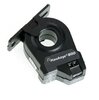
| Current Measurement Range | : | 0.25 - 200 A |
| Current Sensor type | : | Current Switch, AC |
| Electrical Wiring Size | : | 24 - 14 AWG (0.2 - 2.1 mm²) |
| Measurement Type | : | AC Current |
This switch (file hawkeye 800)runs about 15$.
Id like to see if I can build it.
Besides the cost this one is big. Id like to make it smaller. For my purpose 20amps is all that i would require.
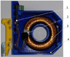
Ive looked at IC types but they require DC voltage to function. I like how this uses the current from the device passed through the cores winding. I mean im unsure how it uses that current and closes a switch. I found this device opened (file current amplifier...) but i cannot tell how it functions.
My goal is to understand how this works and make one that does the following...
detects up tp 20amps of AC using the "hall effect"
while the current is 0 the switch is open
when it does detect current the switch closes
when current is 0 the switch opens again
It needs no external power to function
I will be connecting it to SW1 on pcb (file workshop)
This circuit (when SW1 is closed) will close relay K1 after a 0-6 second delay. when SW1 opens relay K1 will open after a 5-15 second delay.
thank you.