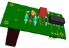
OK. I believe i have this correct now.
Added (4148) across the coil of the relay
Used ground from Workshop circuit. It comes in from SW1 pin 1
Re-routed 12v to connect to just the positive side of relay coil (NA-12WK)
12v supply from SW2 pin1 of workshop circuit
View attachment 132686
--------------------------------------------
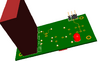
All components will be on a custom made board to fit this box.
The CT will protrude from the box on the other side of the circuit board
low voltage connections will be supplied to box via 3 pin plug from workshop circuit
Distance from each box is apx 5 inches. they are completely isolated from one another
View attachment 132682


")
 ).
).