ThomsCircuit
Well-Known Member
Sorry friend. I was just being funny. I implemented the suggestion right away. Thank you.I don't understand your comment.
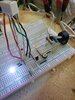
The track just looked like it could be routed more efficently and kept away from the AC end of the board.
")
 )
)