Hello again,
Very good Heidi")
It is good that you thought to use the DC analysis instead of transient.
Also, i realized we could have used the DC sweep analysis
I dont use LT Spice as much as others here i think, but i still like to use it from time to time. It works pretty good for free program. Thanks go out to Linear Tech for giving us this tool.
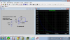
As a final note, we can see how the gain affects the voltage at Vn by sweeping from 1k to 50k. That shows us how the change levels off as the gain reaches roughly that upper limit of 50k. After that an increase in gain doesnt buy us too much more. Later when the transient response is done it will matter more though where the gain cuts back with frequency. At that time we'll want as much DC gain as we can get.
Very good Heidi
It is good that you thought to use the DC analysis instead of transient.
Also, i realized we could have used the DC sweep analysis
I dont use LT Spice as much as others here i think, but i still like to use it from time to time. It works pretty good for free program. Thanks go out to Linear Tech for giving us this tool.
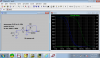
As a final note, we can see how the gain affects the voltage at Vn by sweeping from 1k to 50k. That shows us how the change levels off as the gain reaches roughly that upper limit of 50k. After that an increase in gain doesnt buy us too much more. Later when the transient response is done it will matter more though where the gain cuts back with frequency. At that time we'll want as much DC gain as we can get.