Continue to Site

Welcome to our site!

Electro Tech is an online community (with over 170,000 members) who enjoy talking about and building electronic circuits, projects and gadgets. To participate you need to register. Registration is free. Click here to register now.

  • Welcome to our site! Electro Tech is an online community (with over 170,000 members) who enjoy talking about and building electronic circuits, projects and gadgets. To participate you need to register. Registration is free. Click here to register now.

How to calculate Dc bias in this circuit

gjoo

Member
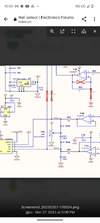
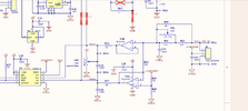
How do you calculate Dc bias in this circuit. VR2 is a potentiometer from O-100k resistance. But, how does the 100 ohm resistor on the output of the op amp play into calculating how much dc bias adds to that op amp output before it's fed to the adc. Wouldn't the potentiometer be ineffective at most settings?
 

Attachments

  • Screenshot_20230611-220343.png
    Screenshot_20230611-220343.png
    433.7 KB · Views: 134
Because of the 100 ohm (and it would be worse if it wasn't there) the 100K will generally have very little effect, but I suspect it's not meant to have much effect, and it just intended for minor balancing, and should be near it's centre. I'm also not happy about the fact there's no resistor top and bottom of the pot, so the 100 ohm can be connected directly to 5V or directly to zero volts, which will have a HUGE effect.

Seems a very poor circuit, where ever it might have come from?.
 
What setting on the potentiometer is the most useful in this circuit. It looks like it's most effective on a low setting, since when used with the 100 ohm resistor, the smaller the resistance in the potentiometer the more effective. 100/1100 is larger than 100/110000
 
What setting on the potentiometer is the most useful in this circuit. It looks like it's most effective on a low setting, since when used with the 100 ohm resistor, the smaller the resistance in the potentiometer the more effective. 100/1100 is larger than 100/110000
The most useful setting is whatever position produces the needed offset voltage.
 
For circuit analysis purposes, if the pot was at 50k, would we calculate the output of op amp point as follows? 2.5(100/50100) + op amp output?
No, as the pot effect will be non-linear - very little effect near the centre of its range, but massive effect near the ends of the range.

It directly shorts the signal to power or ground at the extremes!
 
With the pot near centre, it allows a small bias offset across the 100 Ohms, relative to the opamp output.
Far from centre, the opamp may distort due to excess current.

The better approaches are such as a lower value pot across the supply with a fairly high value resistor to feed the bias, or a pot with the wiper direct connect as in the circuit you show, but with resistors from the ends of the pot to power and ground to restrict its adjustment range so it cannot have any detrimental effect at extremes.

Better still, put it at an input - eg. add a low value pot in the centre of the bias divider that feeds pin 3 of the opamp in that circuit, so the level can be directly calibrated.

However the circuit looks to have more problems than that oddball bias pot!
 
That may work, as long as the lowest resistance end of the pot is still far higher than the 100 Ohm.

Allow for the Thevenin equivalent of the pot - which changes with its setting.
 
One change that I would suggest is to connect the top of the pot to the 4.096 Volt reference instead of +5 Volts.

You don't show the rest of the schematic, but it's easy to assume that the 5V rail feeds many other parts, and is likely to be noisier less stable than the 4.096 Volt reference.
 
These OA's have 1.7 mV offset max so the solution chosen here was to only use the middle few % range of the trimpot to offset a few % of 100k loaded by 100 ohms towards a 2V offset. Thus a 10% offset on the pot or 60k,40k which is 100/24k * 10% of 4.096V/2 for a Thevenin offset is 844 uV. So the useful range is < +/-20% estimate then it far exceeds spec'd offset.

Well that's one way to do it. but not one I would use.
 

Latest threads

New Articles From Microcontroller Tips

Back
Top