Continue to Site

Welcome to our site!

Electro Tech is an online community (with over 170,000 members) who enjoy talking about and building electronic circuits, projects and gadgets. To participate you need to register. Registration is free. Click here to register now.

  • Welcome to our site! Electro Tech is an online community (with over 170,000 members) who enjoy talking about and building electronic circuits, projects and gadgets. To participate you need to register. Registration is free. Click here to register now.

How can I clip voltage faster?

Status
Not open for further replies.

Thomas Anderson

New Member
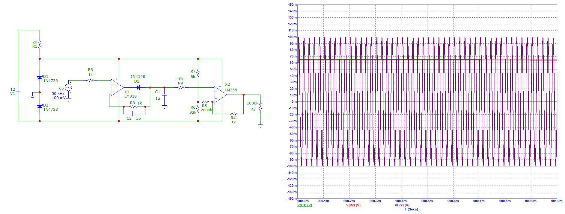
I have this test circuit, which has this signal:
eac034cc7716b2cd7330a.png

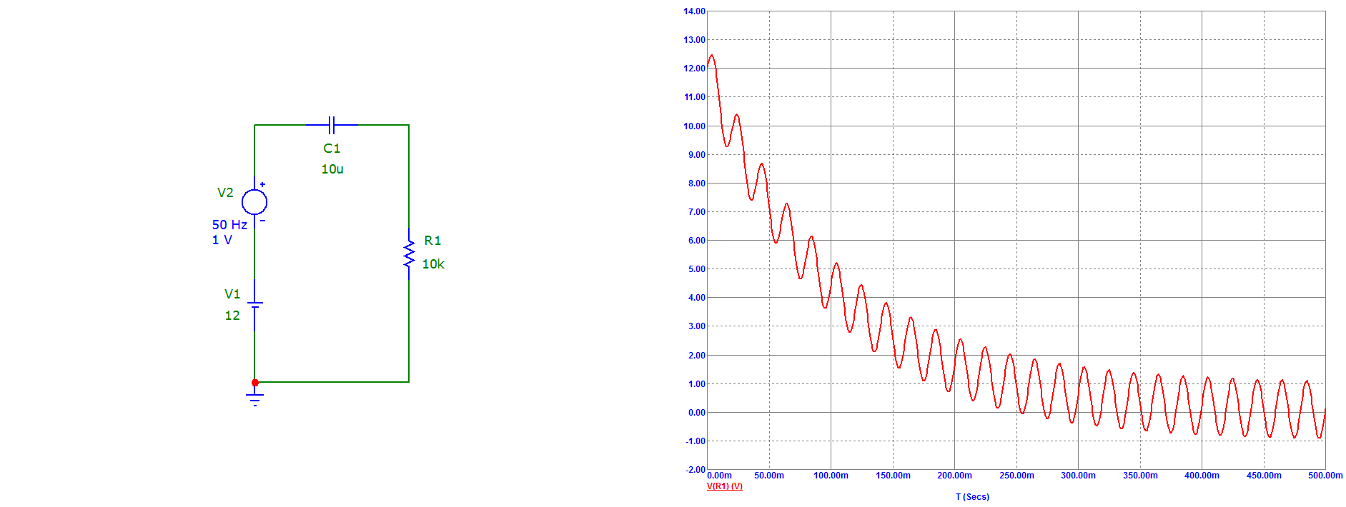
V1 may change from 1 to 30 V, V2 may change from 0 to 4 V peak to peak.
I need to clip the signal at about 3 - 4 V to feed it to an Op Amp, which has a split supply voltage of about -5 and +5 V.
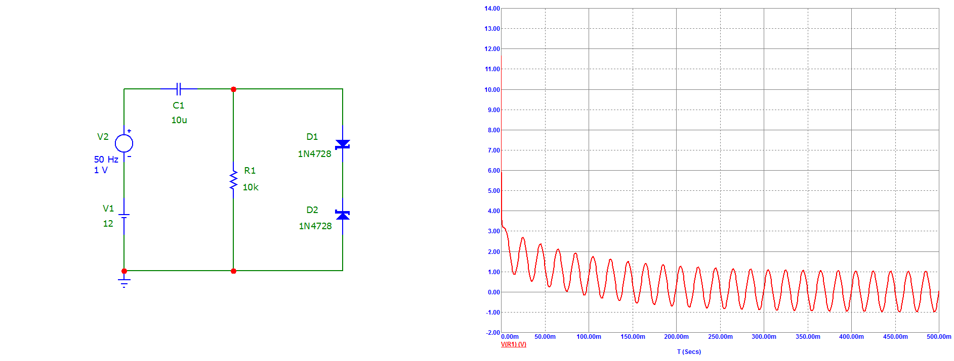
So I added two zener diodes and the signal was clipped:
34267eb4bb721245a203c.png

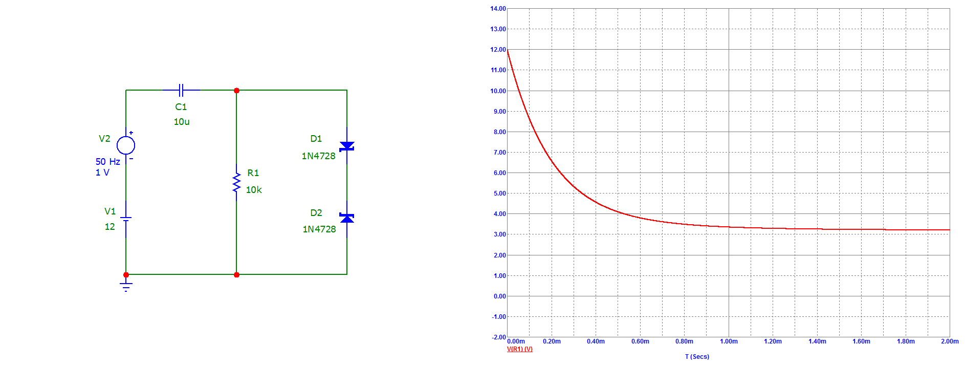
But it was not fast enough, for about 300 microseconds the signal was still above 5 V - the Op Amp power supply voltage, which, I figure, may damage the Op Amp:
79f77c7525131a89584fa.png

How can I clip the voltage faster, without distorting the signal that is below 3 - 4 volts?
 
Add a resistor in series with the capacitor, somewhere around 100 Ohms to 1K.

That should limit the current through the zeners and allow them to regulate the voltage better.
 
Thank you, rjenkinsgb! That does work. Although at higher resistance it attenuates the signal, so it is going to be a bit of a trade-off.
 
If you put a resistor in series with the op amp input (e.g. 10kΩ) with two small Schottky diodes, one from the input to the V+ supply (cathode), and one from the input to the V- supply (anode), the op amp should be protected from any input overvoltage without affecting the signal amplitude below that..

What is the input impedance of the op amp circuit?
 
What about shifting the Non inverting input maybe 1 or 2 V "upwards"?
Otherwise, just making +Vcc higher like 9 V?
 
If you put a resistor in series with the op amp input (e.g. 10kΩ) with two small Schottky diodes, one from the input to the V+ supply (cathode), and one from the input to the V- supply (anode), the op amp should be protected from any input overvoltage without affecting the signal amplitude below that..
Thank you, crutschow, that does help.

What is the input impedance of the op amp circuit?
That I have not determined yet.

What about shifting the Non inverting input maybe 1 or 2 V "upwards"?
Otherwise, just making +Vcc higher like 9 V?
Thanks for suggestions, atferrari. No, unfortunately, I can not add DC to the signal, because I need to rectify it. Also I can not make +Vcc higher, because the power supply is 12 V single, and I am making a dual out of it with a virtual ground. And it has to be symmetrical.

But solutions proposed by rjenkinsgb and crutschow solve this problem.

Unfortunately, now I ran into another problem, and I am stuck figuring out if my project is feasible at all. Maybe it is not. I was thinking about making a peak detector that was supposed to work from 20 Hz to 1 MHz. Now it works well at low frequencies, but I see a significant signal attenuation already at 50 kHz.

e98eb3fd2bc9f55917702.png


I do not understand why it happens, because both the diode and the Op Amp should perform well at 1 MHz. I am reading a textbook on Op Amps now, but maybe this project is not doable at all. Thanks for the help, guys, anyway, those were good lessons for me.
 
Status
Not open for further replies.

Latest threads

New Articles From Microcontroller Tips

Back
Top