Continue to Site

Welcome to our site!

Electro Tech is an online community (with over 170,000 members) who enjoy talking about and building electronic circuits, projects and gadgets. To participate you need to register. Registration is free. Click here to register now.

  • Welcome to our site! Electro Tech is an online community (with over 170,000 members) who enjoy talking about and building electronic circuits, projects and gadgets. To participate you need to register. Registration is free. Click here to register now.

High component count for long delay circuit (inrush resistor switch out)

Status
Not open for further replies.

Flyback

Well-Known Member
A long , and very robust delay is needed for the delay to switch the inrush resistors out.......has to be robust because an un-limited inrush from 240VAC mains peak into 4.3mF will kill the PSU and blow the breakers, as you know....though can you think of how to reduce the component count here?...without using a micro
LTspice and scm attached.
 

Attachments

  • inrush delay _555 delay.asc
    17.7 KB · Views: 185
  • Long delay for inrush resistor switch out.jpg
    Long delay for inrush resistor switch out.jpg
    158 KB · Views: 212
Is the posted circuit not working?
What help do you need?
 
I know you don't want to give away any top secret information, but . . .

How long?

ak
 
The delay needs to be long enough for 4.3mF to charge up to line peak throughout 100-265VAC and 23.5R inrush resistor....so we're talking, to be safe, 3 seconds.
 
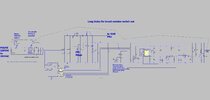
That is a *lot* of parts. Please explain its operation.

Also . . .

Why is there a 1.4 kHz oscillator gated on and off at a 120 Hz rate, in the middle of a PFC circuit? Are you creating a delay by integrating cycles of an oscillator?

What is the purpose for D2?

Q1 applies a dead short to GND across the +5 V rail.

Delete R8.

Choose a different comparator and eliminate the 5 V supply, along with almost everything to the right of U2.

If you reverse the inputs to U2, you can eliminate Q13, R46, R47.

The M4 drain current is less than 60 mA. If you change M4 to a small logic-level FET, you can drive it directly with U2, and eliminate Q3, Q13, R8, R10, R45, R46, R47, R48. If you run the entire circuit on 12 V, M4 could be something simple like a 2N7000/7002.

Connect the U2 and U5 non-inverting inputs together, and delete R6, R7, C4.

There is no base current limiting for Q14.

You have two bridge rectifier circuits essentially in parallel. Connect the D14-D16-C10 node to the R9-C15 node through D21, and eliminate D22, D23, D24.

Why not put R29 in series with D18? It would switch off itself when the boost converter kicks in.

What is the discharge path for C9?

C10 degrades the effectiveness of the PFC stage. What is its purpose?

Delete R40 or R41.

What is the purpose of R48?

There is no capacitance in the Q11 base circuit, so Q8 is constantly applying discharge pulses to C3 at a 120 Hz rate.

I think U1, U5, and almost everything around them can be replaced with a simple R-C ramp going into U2.

ak
 
Last edited:
The delay needs to be long enough for 4.3mF to charge up to line peak throughout 100-265VAC and 23.5R inrush resistor....so we're talking, to be safe, 3 seconds.
So, the idea here is to have a guaranteed minimum inrush limit period, that resets almost immediately after power is removed so that if power bounces quickly, you still get the full inrush protection time?

If all of that is correct, then, again, what is wrong with putting the current limiting resistor in series with a diode (that eliminates the relay), and adding a small turn-on delay to the PFC controller chip's enable or UVLO input?

What is the part number of the PFC controller chip?

ak
 
Thankyou for your great comments here AnalogKid! Much appreciated.
Thanks, PFC chip is UCC28080A...its disabled by pulling its soft start down

Why is there a 1.4 kHz oscillator gated on and off at a 120 Hz rate, in the middle of a PFC circuit? Are you creating a delay by integrating cycles of an oscillator?
Thanks, the 555 was just so i can use a smaller delay capacitor.
What is the purpose for D2?
...just in case of any stray inductive effects.
Q1 applies a dead short to GND across the +5 V rail.
...Thankyou!...Massive Thankyou!...i totally missed that.
Delete R8.
..Thanks Again!
What is the discharge path for C9?
...My apologies for not showing more of the circuit...there are a number of dividers to ground from C9...also, it is the input cap to the LLC converter, and another 30W flyback converter.
What is the purpose of R48?
Thanks....nice spot, i accidentally left it in from when the rail there was 24V.

There is no capacitance in the Q11 base circuit, so Q8 is constantly applying discharge pulses to C3 at a 120 Hz rate.
Thanks, i can see what you mean, the idea was originally that C15 would be made big enough to keep opto U4 conducting enough all the time to keep Q11 always ON in saturation.

So, the idea here is to have a guaranteed minimum inrush limit period, that resets almost immediately after power is removed so that if power bounces quickly, you still get the full inrush protection time?
Thankyou...yes indeed, thats exactly it.
 
Last edited:
why don't you just use a NTC thermistor like everybody else in the world? one part will solve the inrush problem.
 
why don't you just use a NTC thermistor like everybody else in the world? one part will solve the inrush problem.
Not for brief input power bounces. 1 second is more than enough time to deplete the PFC output capacitance, but not nearly enough time for an input NTC to cool off enough to increase its resistance.

In the Westcor (Vicor) MegaPAC modular supply, they solved this with a relay that shorts out the input NTCs once the supply is up and running. Rapid cycling of the input still was a problem.

I worked on a compromise design, where the big caps are pre-charged through a diode and NTC. Once the supply was up, the diode disconnected the NTC so it could cool down completely. If the supply was up for several minutes, we got full inrush mitigation even with a short power bounce. This got rid of the relay and its driver circuits, but we still had the same problem as the MegaPAC - if a power bounce came shortly after the supply was turned on, the NTC didn't have enough time to cool off so we still had a large inrush in some situations.

With a diode-connected, non-NTC fixed resistor as the pre-charger it takes longer to pre-charge the PFC caps, but there is no thermal time constant to deal with. Pre-charge performance is consistant no matter when the input power bounces. I think that this, plus a PFC controller with decent soft-start, is the way to go.

With an input current of 40 A, a relay is a problem. Also, the impulse power dissipated in the TS resistor is around 2400 W. This circuit is by no means a simple problem to solve.

ak
 
Last edited:
Just control the shunt relay by directly monitoring (analog reading) the DC bus voltage & keeping the load disabled until it's at full level.

That's what most high power industrial systems, do like Siemens and Bosch etc.

If you use a small MCU for voltage tracking, timing and output control, the whole thing becomes very simple.

KISS principle, not a Heath Robinson monstrosity like that diagram!

You MUST also control the load enable, otherwise it will draw current as the star-up circuit is trying to charge the system and prevent it or slow it down.

Keep considering the overall system requirements, not only the subsections.
 
Thanks for that article...i am not sure about that doc...because on 6th page (marked pg 5), they say....
(regarding operation above the resonant frequency)....
QUOTE.....
**The rectifier diodes are not softly commutated and reverse recovery losses exist**

...this is completely wrong....and is a basic situation of the LLC converter.
And it is in fact, common to operate an LLC above f(res), because you are further from the capacitive region....and your RMS and peak output current is lower.....
 
I must admit it was a surprise to see such a generally excellent article about LLC converters getting the most basic aspect of them totally and utterly wrong.
 
I must admit it was a surprise to see such a generally excellent article about LLC converters getting the most basic aspect of them totally and utterly wrong.

Contact TI, I am sure they would want to revise the app note.

I am reading an Infineon ap note, as I am new to LLC, and they clearly state -

1652348985937.png


Regards, Dana.
 
Status
Not open for further replies.

Latest threads

New Articles From Microcontroller Tips

Back
Top