Help troubleshooting LED sequencer?
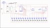
Im pretty new to all this but ive worked this up. evertime i press the button it goes to the next LED. I will be using this as the basis for a cable tester. the only problem is that there is a pause between LED 8 and LED 9, the switchover between 4017's. another small thing when the simulation starts up it lights up a few random LED's untill i depress the button. could just be a simulation error.
Im pretty new to all this but ive worked this up. evertime i press the button it goes to the next LED. I will be using this as the basis for a cable tester. the only problem is that there is a pause between LED 8 and LED 9, the switchover between 4017's. another small thing when the simulation starts up it lights up a few random LED's untill i depress the button. could just be a simulation error.
Attachments
Last edited:
")