Continue to Site

Welcome to our site!

Electro Tech is an online community (with over 170,000 members) who enjoy talking about and building electronic circuits, projects and gadgets. To participate you need to register. Registration is free. Click here to register now.

  • Welcome to our site! Electro Tech is an online community (with over 170,000 members) who enjoy talking about and building electronic circuits, projects and gadgets. To participate you need to register. Registration is free. Click here to register now.

Help with LED sequencer

Status
Not open for further replies.
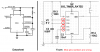
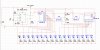
so i found that the circuit would reset if i ground out pin 6 of the 555 through the 10uf cap. i couldnt get that 18 led model to work. i have led17 and 18 in there for a visual reference ( was trying to figure out what was going on) anyway i thought i would attach the file it seems like that might be more useful since its being weird.
 

Attachments

  • Circuit 04.jpg
    Circuit 04.jpg
    864.6 KB · Views: 906
  • Cable Tester 4.zip
    217.9 KB · Views: 249
Your latest schematic has a few pin numbers wrong on the 555 timer.
 
hmm? i havent changed any of the pins. on the 555 i just changed the viewing options so that it displays the pin numbers

edit
i did add the grounded pin 6 through the cap, but that seemed to fix the reset problem
 
Last edited:
i think the footprint with regards to the pin numbers is wrong in MultiSim if i plug the stuff using the pin numbers as a guide it doesnt work at all.

thanks guys for not giving up on me. that pause between 8 and 9 is just sucking the life out of my soul.
 
You can make a CD4017 count backwards by adding diode OR gates to the outputs.
Knight Rider circuits use diodes so that the LEDs wag back and forth.

I am designing a Knight Rider circuit to drive very bright LEDs. I am using Bill Bowden's cascaded CD4017s circuit. Four diodes are two AND gates. The diodes at the outputs are OR gates so that one CD4017 lights the LEDs in one direction and the other CD4017 lights the LEDs in the other direction.
 

Attachments

  • Luxeon Knight Rider LEDs.PNG
    Luxeon Knight Rider LEDs.PNG
    24.7 KB · Views: 1,798
ok so i think i managed to fix it. i changed the value of C2 coming out of the 555. does this seem like a reasonable change. there is no pause when it switches from U4 to U5 now.
 

Attachments

  • Circuit 04.jpg
    Circuit 04.jpg
    922.8 KB · Views: 2,184
ok so i think i managed to fix it. i changed the value of C2 coming out of the 555. does this seem like a reasonable change. there is no pause when it switches from U4 to U5 now.
The value of C2 determines the amount of waiting time until you can push the button again. Before you needed to wait for about 0.1 seconds and now the waiting time is only 0.001 seconds.

Didn't you want 16 LEDs? Now you have 17. It is easy to remove the last LED and connect its output to reset the left counter.
 
yeah i just wanted to rule everything out before i took it back down to 16.

i definitely learned a ton designing this and trouble shooting stuff.
i ended up going with a 100pf cap on that one. everything seems solid.

now im gonna work on prototyping the pcb. figuring out which footprints to use seems like it might be fun. :-(

thanks again everyone. hopefully ill have some more stuff in the works soon.
 
Replace the two 4017s with a 4514 4-to-16 line decoder ( logic "1" output), and use a 555 to clock the 4514 at a preset rate. If you can, use identical open sockets to connect the cable between the IC and the LEDs. Your circuit lacks an LED for power and clock pulse.
My experimental design used a 7493 with a 74154, powered by a wallpack and 78L05 regulator. Too many connectors spoiled the appearance.
Try this circuit for an automated checker:
 

Attachments

  • xmaslights.gif
    xmaslights.gif
    71.5 KB · Views: 354
Last edited:
Don't try it before you put some current limiting resistors on those gates and LED's!
 
The LEDs in the opto-isolators are not connected to 0V so they won't do anything.
The typical output current of a CD4017 driving a 1.3V IR LED (in the opto-isolator) from a 9V supply is only 15mA. But the max allowed dissipation in an output transistor in the CD4017 is 100mW and here the dissipation is 7.7V x 15mA= 116mW so current-limiting resistors are needed to share the heat.
 
Last edited:
so currently i have a push button that advances which led is lit by one.
BUT...
what would it look like if i wanted to have a button that would decrease it by one. basically letting me go forward or backward one led at anytime.
 
A completely different circuit using different parts can have the count advance by pushing one button or decrease by pushing another button.
 
You could reduce your parts count by using a 4514 ( output "1") or 4515 ( output "0"), driven from a 4520 binary counter. A bounceless switch using a 4011, along with a slow scan clock from same IC, can improve the versatility of this project.
 
21 led's

Hey everyone! First post! I'm not trying to hijack this thread...But How would you change this set up to allow for 21 led's. This will be my first electronics project. Thanks for all the help in advance.
Ryan
 
Hijacker! Well, not really -

You can cascade the 4017. There's a diagram on the spec sheet that shows how to do it. You have to add an "AND" gate at each stage, but you can string together as many as the fan-out from the clock will allow (usually 10).
 
Thanks for the help

Thanks Duffy!
I'm going to sound really new but where do I find the spec sheet? I Know what I want to do. It's just I'm having a hard time trying to figure out how to get the right set up. If I had a diagram in front of me with all the components I need I have no doubt I could put it all together.
Again thanks for helping out the "VERY" new guy.
Ryan
 
Status
Not open for further replies.

New Articles From Microcontroller Tips

Back
Top