Continue to Site

Welcome to our site!

Electro Tech is an online community (with over 170,000 members) who enjoy talking about and building electronic circuits, projects and gadgets. To participate you need to register. Registration is free. Click here to register now.

  • Welcome to our site! Electro Tech is an online community (with over 170,000 members) who enjoy talking about and building electronic circuits, projects and gadgets. To participate you need to register. Registration is free. Click here to register now.

Help Needed to Reset..CD 4017..?

Status
Not open for further replies.
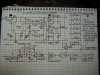
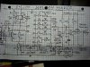
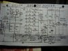
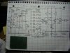
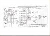
UPDATE ON MELODY MAKER : Thanks for responses.. Finalized and tested on breadboard attached circuit.. I can now play 6 sequential notes (6th.note twice longer) by presssing the button once, as required.. However I have to set the timer circuit exact lenght of ending time to end the melody if set longer goes back to start to play few more notes until timer stops. Thought but not really successfully
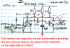
achieved to Reset 4017 after the 6th note. therefore used the timer.. is there a way to Reset without using timer..The summed and tuned outputs from 4017 are not directly amplifiable..tried on 555 as shown in previous schematics just creates buzzy noise as output.. Therefore used 2 Transistor Bistable Osc. to convert the pulsed outputs to Sinewave then send to the suitable Amp. used LA4440 and worked for me. is there an IC with required Osc. built in as well as more amplification..? when I install in a car so it can be heard more..? Need to know how to Reset back when Melody ends and Which IC I can use to amplify the summed output notes..and importantly..how to stop whole circuit drawing current when Melody ends.. until button pushed to turn on again.. Any inputs to the attached circuit will be appreciated.. Thanks All.
 

Attachments

  • DSCI0218.JPG
    DSCI0218.JPG
    657.2 KB · Views: 540
I can't understand how your reset works with the diode and 100k resistor. Can you explain your reasoning ?
This is how I would design the unit to work without the timer 555.

Tune.png

I have also modified the way the last note is done so you only have one trimmer to set the frequency. The 4017 part of the circuit must be powered all of the time. (It will only consume a few micro amps.) S1 is a push to make button. The 4017 will be in state 7 (After the end of the long sixth note in states 5 and 6) When the button is pressed it resets the 4017 to state 0 so the output of state 7 goes low. this turns on transistor Q1 which supplies power to the rest of the circuit until state 7 is reached which turns off Q1. The maximum current that this transistor can supply is 100 mA so if you need more then the circuit will need modifying.
Note the schematic was drawn with Eagle PCB software which is free. Let me know if you would like the eagle file for the schematic.
Les.
 
When the reset pin #15 of the CD4017 goes high then the CD4017 is reset so that Its first output Q0 which is pin #3 goes high. The capacitor connected to pin #15 and to the positive supply provides a positive pulse to pin #15 when the power is applied then the capacitor quickly charges by the resistor to ground at pin #15 which allows pin #15 to go low.

Teknofix showed pin #15 connected to a diode on his last schematic then the pin #15 is floating and could be high or low.
 
Hi AG,
That is also my understanding which is why I asked the question. Can you see any problems with my suggested schematic in post #22 ? The diode D8 is being over cautious to prevent a negative pulse to the reset pin when the power goes low.

Les.
 
The output of a 555 or a 2 Transistor Bistable Osc. produces a squarewave that sounds like a buzzer. You probably want a mellow sinewave tone so you need a voltage controlled sinewave oscillator.
On the 2 Transistor Bistable Osc. you show a resistor and capacitor not connected to anything. Maybe they are connected to the base of the transistor on the right side as a simple filter that changes the squarewave into a triangle wave.

Later you can add circuits to control the attack and decay of the tones.
 

Attachments

  • bistable osc.png
    bistable osc.png
    149.6 KB · Views: 316
The output of a 555 or a 2 Transistor Bistable Osc. produces a squarewave that sounds like a buzzer. You probably want a mellow sinewave tone so you need a voltage controlled sinewave oscillator.
On the 2 Transistor Bistable Osc. you show a resistor and capacitor not connected to anything. Maybe they are connected to the base of the transistor on the right side as a simple filter that changes the squarewave into a triangle wave.
Later you can add circuits to control the attack and decay of the tones.

**** Teknofix Wrote : ****

Thank you observing the mistake made when drawn..attached the correction, with this 2 transistor Astable Osc. circuit was able to convert pulsed outputs of 4017 into audible tones to send to a suitable Amp, tone control achieved varying input pulses thro 22K trimpot. into Bistable Cct. would like to correct the 4017 Reset problem and omit Bistable, instead use more suitable IC. capable of converting 4017 pulses into more mellow audio tones to be amplified. any suggestions..?
 

Attachments

  • DSCI0219.JPG
    DSCI0219.JPG
    214.4 KB · Views: 310
I can't understand how your reset works with the diode and 100k resistor. Can you explain your reasoning ?
This is how I would design the unit to work without the timer 555.

View attachment 97650
I have also modified the way the last note is done so you only have one trimmer to set the frequency. The 4017 part of the circuit must be powered all of the time. (It will only consume a few micro amps.) S1 is a push to make button. The 4017 will be in state 7 (After the end of the long sixth note in states 5 and 6) When the button is pressed it resets the 4017 to state 0 so the output of state 7 goes low. this turns on transistor Q1 which supplies power to the rest of the circuit until state 7 is reached which turns off Q1. The maximum current that this transistor can supply is 100 mA so if you need more then the circuit will need modifying.
Note the schematic was drawn with Eagle PCB software which is free. Let me know if you would like the eagle file for the schematic.
Les.

*****Teknofix Wrote : ****

Les, thank you for responding, attached and explained circuit suggestion, effords appreciated.. I will certainly built this circuit on breadboard to try and will let you know the results. was recomended to connect 1 Meg Resistor from ground to Diode to reset pin 15 and 0.1mf cap to +Vdd. in previous Reset suggestions. used 100k and Diode instead, omitted 0.1mf.cap since did not make any difference,but still not fully achieved
to Reset when last note is played. therefore was able to achieve Stop by adjusting the timer to lenght of the melody. My aim is : by pressing a button once, to be able the play
set melody to end then Reset back ready to play again.. regardles how short or long the
555 timing is set . I am planning the install and use it in car so needs to working with +12VDC and must have powered amplification to be heard on traffic noise. Trying to figure out Simpler and Powerfull configuration suggestions to what I am building :
so called : Melody Maker Circuit using 555 - 4017 and Amp combinations.
I am certainly interested in Eagle PCB Software to see and try, I am professional Electronics tech retired from Motorola, since I live alone don't know what is going arround lately..thanks for informative and helpfull suggestions. correction in Bistable CCt is attached. Teknofix. Teknofix@hotmail.com
 

Attachments

  • DSCI0219.JPG
    DSCI0219.JPG
    219.3 KB · Views: 276
Voltage-controlled sinewave oscillator ICs were used many years ago but are obsolete today. Recently I made a simple Cmos voltage-controlled square wave oscillator that clocked a digital counter at a fairly high frequency. I used resistors on the counter's outputs so that they made a stepped sinewave. It was easy to filter away the high frequency steps and the result was a pure sinewave with its frequency controlled. The CD4017 would sequence DC voltages to control the frequency. You can doo dat.
 
I can't understand how your reset works with the diode and 100k resistor. Can you explain your reasoning ?
This is how I would design the unit to work without the timer 555.

View attachment 97650
I have also modified the way the last note is done so you only have one trimmer to set the frequency. The 4017 part of the circuit must be powered all of the time. (It will only consume a few micro amps.) S1 is a push to make button. The 4017 will be in state 7 (After the end of the long sixth note in states 5 and 6) When the button is pressed it resets the 4017 to state 0 so the output of state 7 goes low. this turns on transistor Q1 which supplies power to the rest of the circuit until state 7 is reached which turns off Q1. The maximum current that this transistor can supply is 100 mA so if you need more then the circuit will need modifying.
Note the schematic was drawn with Eagle PCB software which is free. Let me know if you would like the eagle file for the schematic.
Les.
*
* Teknofix wrote : 4017 power connection to pin 16 not shown, assuming connected directly to +12v. since has to be on all time. (but 555 to SW) ?
 
Eagle schematic software does not show the power connections to the IC itself. It shows all the power connections seprately. It you look at the bottom right of the schematic next to C1 you will see IC1P. This is the power connections to the 4017. It does make the schemaitic less cluttered. I was assuming that the unit ran from batteries so that is why I added the transistor to remove power from the rest of the circuit when it was not playing the tune. As you are running it from a car battery you could leave the rest of the circuit powered up all of the time. If you did that R9, R10 and Q1 would not be needed. When I suggested the diodes in the reset circuit in post #7 I thought you wanted the tune to play over and over. The two diodes formed an "OR" gate so the 4017 would reset on power up via one diode and also reset after the last note was played via the other diode. The diodes would not be connected in series with the resistor to ground from the reset pin. You can download Eagle software from here.


Les.
 
Yes,now I see the marked power connections to 4017 at bottom and undrestand the reason.
haven't tried the given circuit yet,but it makes sense, omitting mentioned 3 parts means whole circuit will be powered all the time although may be drawing negligible current from car battery, therefore I powered the cicuit from 555 timer for: timing to play the melody then turn off rest of the circuit, until the button pressed to turn on the timer again. since
if I can achieve Stop and Reset at last 2 notes with circuit powered all time..(concerned unnecessary current flow when not used) may be 555 timer powering is unnecessary ? Also I need to find out a suitable IC to convert and amplify the summed 4017 pulse outputs into audiable (mellow) tones to send to Speaker. will post the results asap as I will try the circuit on breadboard. Usually drawing schematics by hand.. would like to download and experiment with Eagle Software, thanks for the provided link.
 
Hi Les, tested your attached circuit worked perfect..! shorting pins 6 and 13 and grounding pin 15 via 100k resistor and diode did the Reset I was trying to achieve..but failed because I was going from pin 6 via diode to pin 13 and from pin 15 100k resistor in series with diode to ground. Anyway since now it Resets when Melody is Played, I omitted the 555Timer. 12V power only applied to 4017 as stand-by.. Q1 is turned on to supply power to 555 Pulse Gen IC, when button pressed adjustable supplied pulses from pin 3 to pin 14 of 4017 starts the output sequence summed with individually tuned notes turns on Mosfet to supply -ve rail to Astable Osc. which shapes the 4017 pulses into waveform to be Amplified. used TDA 2030 IC to drive 20w/8ohm Speaker achived satisfactory output..but still need to figure out to use more powerful output IC. since the speaker will be somwhere in the car bonnet next to running engine..any suggestons..? Don't know if you notice I did some modifications, replaced 100n cap with 100k resistor from pin 15 to trigger end of +Vdd Push button. also swapped Diodes and 500k Trimpots, for easy line-up of outputs on PCB. Can I possible use LED Diodes instead of 4148 so I can have a Visual display while the Melody is Playing..? however I added LED shows duration of Melody only. Tried to download the "Eagle Sotware" from given link..but when click to download, I get "404" Error ! ...Couldn't figured out, so Draw the whole Circuit by hand..corrected some mistakes and rechecked..Could you Please take a look...see if needs any correction or modification..? Also let me know if you can Draw this with Eagle Software.. and if I can too..? Interested to Download and Practice to stop drawing by hand and ruler..! Thanks in advance.. T e k n o f i x .
 

Attachments

  • DSCI0223.JPG
    DSCI0223.JPG
    286.9 KB · Views: 316
I don't understand why you replaced the 100 nF capacitor with a 100 K resistor. This means that when the end of this resistor is at +12 volts you will be applying + 6 volts to the reset pin which is an undefined logic level. (This means it could be interpreted as either a logic zero or a logic one.) Can you explain your reasoning ? From your new schematic it looks like the reset pin (15) is connected to the wrong place. I do not think it is a good idea to replace the diodes with LEDs. 1 You will exceed the LEDs reverse voltage rating. 2 You will subtract the LEDs forward voltage drop from the output pins of the 4017 which can be between 1.8 and 3.3 volts depending on your choice of LED. Also the forward voltage drop of LEDs is temperature dependent so the frequency will change with temperature. 3 The current through the LEDs will be very low so they will be very dim. (The current will be less than 24 uA when the preset is at maximum value.) Why did you not use the switched +12 volt from the collector of Q1 to control the power to the astable and amplifier ?

Les.
 
Les, sorry for bad focus on previous Drawing, attached is much readable compare to previous upload..forgot to mention reason for change 100n Cap to 100k Resistor, if you want o play Melody again or repeatedly..need to wait few seconds..after Melody is Played ( with 100n Cap.) *Replacing with 100k Resistor enabled Melody to be played repeadetly.. Asked if Diodes can be replaced with LED's ? * concerned Leds current draw may distort/change Fine Tuned and Summed 4017 Outputs. Would like to see attached Schematics drawn with Eagle Software for better understanding and visual ease. Thanks. T e k n o f i x .
 

Attachments

  • Melody Maker.JPG
    Melody Maker.JPG
    270.2 KB · Views: 300
The problem you had having to wait a few second before the sequence could be restarted was that the 100 nF capacitor had not discharged. I thought that the load that the pulse generator etc applied to the switched 12 volt rail would have discharged the capacitor quickly enough. This change should fix the problem.


Tune_02.png


I gave you the link to download the fee Eagle software in post 30.

Les.
 
Les, thank you responding.. will put 100n cap. back and 100k res. to ground.as shown in your drawing. Also,
Good idea to supply 12V (+ve) to astable and TDA 2030 Amp. from Q1 switched supply, concerned the total current drawn, recomended Transistor or use the Mosfet as shown but only can switch the (-ve) rail ! with (+ve) input to Gate, how can I switch 12V (+ve) with Mosfet, like Q1 does ? Checked pin 15 goes to collector of Q1 via 100k. resistor used instead of 100n. cap.in your drawing. what is wrong ? Ok. bad idea to use LEDs as accurate freq. required. used only 1 Led shows on while Melody beingPlayed. * Swapping Diodes and Trimpots order will it affect the 4017 outputs ? Any 12V Power Amp.IC with built in Astable ? will try the circuit with mentioned modifications and let you know if ok.
Regarding the * Eagle Software : * followed given link to Eagle Software to Download but receiving "404" error..?
(as mentioned in previous post). * Suggestions appreciated. --------- T e k n o f i x.--------

*** Here found Resetting 4017 from any pin info. attached.how reset pin 15 is connected.
 

Attachments

  • 4017 Reset.gif
    4017 Reset.gif
    13.3 KB · Views: 2,492
You could use a P channel mosfet to switch the positive rail to the astable and audio amplifier. Find a suitable P channel mosfet and I will re draw the schematic.. You could also use a relay. If you decide to use a relay you may need a transistor with a higher current rating than the BC557. This will depend on the coil resistance of the relay. (Don't forget to put a diode across the relay coil to prevent the back EMF when the transistor switches off from destroying the transistor.) The bottom schematic in yor post (#36) uses the same method that is uses in my circuit to hold the 4017 in a state. I uses a different way to stop the pulse generator. It holds the 555 in the reset state rather than removing the power to it. You will not find an audio amplifier chip with a built in astable. I have just tried downloadeing the windows 32 bit version of eagle and it downloaded without a problem. I do not know which version you wanted.

Les.
 
ALMOST COMPLETED..
Les, thank you for suggestions.. Yes, I would like to switch the (+)ve rail with P Chnl./Mosfet to power the rest of the circuit. particulary power amp IC's draw quite a bit current, so couldn't power +12V. all from Q1 but 555 only ! Adding
N Chnl./Mosfet was easy to switch (-ve) rail to power rest of the circuit, tested current drawn with 12V Bulb Ok.
However couldn't figured out, how to use P Chnl/Mosfet to switch (+ve) rail instead. experimented with various configurations with IRF 9540 P Chnl Mosfet without any success...since P / Mosfets requires (-ve) input to Gate to switch the Source to Drain and 4017 outputs are (+ve) pulses..didn't work ! as you apply +12V to Source, Drain also becomes +12V without any input to Gate.. I may be doing something wrong..? How do I switch the (+ve) rail from
4017 summed output, or even from Q1 Collector, to power rest of the circuit ? Have applied the modification and re-draw attached circuit,tested works fine..please take a look if everything looks ok. or not ? I omitted the Diode at pin 15
to Gnd. since did not make difference. as you can see from the picture, I have 18 x 24 Dot Matrixed thro' hole PCB
with very limited space to designate and squeeze the whole circuit in.. no space to use Relay but Mosfet is ok. if you can quide me how to make necessary connections to use the P/Mosfet instead. Good news is , just to let you know, was able to download the Eagle Software (64bit) from different source (epectec) ver.7.4.0 now have to learn how to use to transfer and draw schamatics with..? since you know how, instructions will be appreciated.. Have a good day..
~~~~~T e k n o f i x~~~~
 

Attachments

  • DSCI0231.JPG
    DSCI0231.JPG
    1.9 MB · Views: 345
Here is how to connect the P channel MOSFET.

Tune_03.png


You will need a heatsink on the mosfet as its on resistsnce is about 0.12 ohms. (P channel mosfets seem to have a higher RDS(on) value than N channel mosfets.) The size of the heatsink will depend on the current it is switching. You should be OK now without the diode as the 100K resistor to the top of C2 should limit the current trying to drive the reset pin negative when the push button opens. I just played with Eagle until I learned how to use it. I think there are some tutorials on the web.

Les.
 
Thank you for re-config with Mosfet. don't know why it didn't work when I tried the same..drain become +12v when I connect the source to +12v. without gate input, guessing held at on state ? Anyway replaced the Mosfet with given modifiation *(see attached-1) bingo..it worked..! simply replaced the Q1 with 9540 also changed the 5k6 resistor to the gate with 10k. don't think need of heatsink, since it will be on for only few seconds. it perfectly resets to next push of button, however if you keep pressed, goes back to output 1 (4017 pin 3) and stays there..you need to pause in between play if want to play repeadetely. anayway this is not a big issue, just wanted to let you know the experiment. The fine
tuned (using 500k multi turn trimmers) and summed outputs don't go to 555 as you indicated, instead goes to 2 transistor Astable Osc. to shape the 4017 outputs into audiable waveform to be amplified. however I would like to use a suitable IC. instead of building 2 transistor Osc. Experimented using the 555 output circuit ( refer to attached-2) as well
as LM741 ansd LM358 as an Osc. only get turn-on -off bump.. or weird buzzing..out. so stuck with 2 transsistor Osc.cct.
should be much better IC package to the the job but couldn't figured out yet. Using any +12v Amp. is no problem..
Attached schematic shows using all 10 outputs, 100 ohm resistor used to power the 4017 is necessary..? This circuit simply does NOT work.!! have a good day.. -------------- T e k n o f i x ---------------
 

Attachments

  • Mosfet Switched.jpg
    Mosfet Switched.jpg
    725.5 KB · Views: 264
  • Melody Maker.gif
    Melody Maker.gif
    100.5 KB · Views: 378
Status
Not open for further replies.

Latest threads

New Articles From Microcontroller Tips

Back
Top