Continue to Site

Welcome to our site!

Electro Tech is an online community (with over 170,000 members) who enjoy talking about and building electronic circuits, projects and gadgets. To participate you need to register. Registration is free. Click here to register now.

  • Welcome to our site! Electro Tech is an online community (with over 170,000 members) who enjoy talking about and building electronic circuits, projects and gadgets. To participate you need to register. Registration is free. Click here to register now.

Help Needed to Reset..CD 4017..?

Status
Not open for further replies.

teknofix

New Member
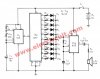
I am building a Melody Maker.. with NE555 andCD4017 to play 6 notes melody.. using the the first 6 outputs (0-5) and ignoring remaining 4 outputs.
I need Melody to start from the first note corresponding output (o) from 4017 counting to the 6th note (output#5) then reset back to (o)
When power is applied (12v) 4017 starts from Random output..intead of starting from (o) so, the Melody does NOT starts from beginning..! and ending soon.I have tried..various INHIBIT and RESET configurations without any success.. How can I make 4017 to start from defined output (0) then Stop at any other defined or after completed cycle..so, when I press the button to apply power (via timer circuit) make sure 4017 always starts from output (0) and
resets back, after completing the counting cycle..which outputs plays the notes of the pre-set Melody. Any help to solve the problem will be greatly appreciated.. 0-1-2-3-4-5-6-Reset back to-0- or, 0-1-2-3-4-5-6- - - - then Reset back to-0- Thank you.
 
You should reset the 555 as well. How about posting a schematic of what you have?
 
I think the easy solution would be to connect a 1M resistor between Reset and ground, and a 0.1uF capacitor between Reset and V+. This should reset the 4017 on power-up. The capacitor conducts when the supply voltage is first applied, pulling Reset high and resetting the chip. When the capacitor charges (it takes a fraction of a second) it begins to act like an open-circuit, so the 1M resistor takes over pulling Reset low, allowing the 4017 to run normally.
 
Last edited:
Here is the similar 555 /4017 sound generator cct. I am using for first 6 outputs to genarate the melody..
having Reset problem to start Melody from beginning and reset to back..when power is applied.
 

Attachments

  • 555-4017 VR.jpg
    555-4017 VR.jpg
    49.9 KB · Views: 702
As DerStrom8 says connect a 0.1 uF capacitor from V+ (Pin 16) to a 1 M resistor whose other end connects to ground (Pin 8). But instead of connecting the junction of the resistor and capacitor directly to the reset pin (Pin 15) connect it via a diode (EG 1N4148) with the diode negative to the junction of the resistor and capacitor and it's positive to the reset pin. also connect the reset pin to ground via a 1 M resistor (Any resistor between 100K and 2.2 M will do) this will reset the 4017 on power up but as you need it to reset after note 6 you need another diode from pin 5 of the 4017 and the reset pin. (+ to reset pin - to pin 5) I think that should do what you want.

Les.
 
?..but as you need it to reset after note 6 you need another diode from pin 5 of the 4017 and the reset pin. (+ to reset pin - to pin 5) I think that should do what you want.

Unless he wants a four-beat pause after the six notes are played.
 
teknofix, I've just re read your original post and realised I have not understood your specification. I thought you wanted to repeatedly play the 6 notes but you want it to stop after playing the tune once. Ignore what I wrote in post #7
Connect the reset pin (15) as DerStrom8 says. (This will cause it to start correctly on the first note.) Disconnect the clock inhibit pin (13) from ground and connect it to pin 5. This will stop the counter incrementing when it reaches state 6. Sorry for the error.

Les.
 
Thank you for responds.. I will try adding 1M resistor and 0.1mf cap. to reset pin and will let you know the results. by the way, I am using 555 timer circuit to power the Melody Maker circuit, when power applied
via push button,(pressed once) as a house bell, timer circuit adjusted to keep the Melody maker (555/4017) on until 6 notes melody played and resets. Here I am attaching another similar circuit I am building but having
problems starting the melody from beginning and resetting after ends. would like to play the 6 notes melody
each time button is pressed to apply power to turn on the circuit then reset back. as circuit starts from random notes..and doesn't resets to first note need more suggestions to correct the problem. Thank you.
 

Attachments

  • MusicBox[1].gif
    MusicBox[1].gif
    6.4 KB · Views: 608
You have been told how to get the 4017 to start in state zero but you have not done this. Instead you have built the circuit again using a slightly oscillator configuration in both 555s. You have done nothing that will solve your problem.

Les.
 
The circuit I built and inquired about.. didn't have chance to apply recomended modifications yet.. as I said, will let you know..
Attached circuits were for better understanding to address the issues experienced, as I said Similar..but Not the exact circuit
with the timer I am building..
 
I think you should use the 555 as a flip-flop, not as a timer. The push button will set it so the melody plays then it resets when the counter gets to next output after the melody is finished.
 
Hi AG,
If the circuit was powered all the time then a flipflop would not be reqired. The bell push could generate a reset pulse for the 4017. The 6 notes would be played (States 0 to 5). State 6 output could be connected to the clock inhibit input which would hold it in state 6 untill the bell push was pressed again. Powering it permanently may not suit the OPs requirements if it was to be battery powered.

Les.
 
Thed schematic in post #5 shows a low capacity 9V battery that would not last long powering the idling 555. Maybe a Cmos 555 should be used which idles with extremely low battery current.
 
If you want to play only six notes each time, all that's needed is to tie 4017 pins 5 and 15 together and remove the unwanted resistors and LEDs.
 
shpkjok,
Everthing you say above is wrong.
1 You cannot connect outputs togeter on devices with active drive high and low. (You can do so with devices with open collector or open drain outputs.)
2 IF the 4017 had open collector / open drain outputs the outputs tied togeter would be low all of the time.
3 There are no LEDs in the circuit. I think you do not know the difference between a diode symbol and an LED symbol.
4 There are no unwanted resistors. The resistors set the frequency of each note. The OP does not want one note for the 6 states that are used of the 4017

Les.
 
Thanks for the responses, here what is worked for me to reset back after 6 notes are played : Connect Diode +side to to Pin 15 then - side Diode to 100K Resistor to Ground. mentioned 0.1mf cap to + 12v and another diode from pin 15 to the pin (last note) to be reset did Not make any difference so, not used.. a 4148 diode from pin 15 to 100k resistor to ground did the trick. Built on breadboard and tested with 6 Leds ok. actually recorded video but unable to upload here..is there a way ? Attached schematics shows
actually what I am building.. first 555 used as 10 sec. timer to power second 555 which supplies adjustable pulses to 4017. decade counter's 8 consecutive outputs routed to 8 pin sil switch to turn any of them on or off if pause needed in between notes. Each 8 outputs are fine tuned to required notes via 500k trimpots and summed outputs send to a suitable Amp. to be amplified to Speaker. in previous schematics 4017 output to 555 shown used as an amp.did Not worked for me..Pulsed outputs from 4017 needs to be converted to SineWave..then amplified..working on 2 transistor Bistable Osc. to treat 4017 pulse outputs then send it to more powerful amp. such as LA4440 etc. Will post the completed
project when finished..wished to be able to attach the video here as well.. if interested drop me a line to: Teknofix@hotmail.com can send it directly. Hope you find it usefull.. Thanks All. TeknoFix.
 

Attachments

  • Melody Maker.JPG
    Melody Maker.JPG
    1.9 MB · Views: 436
Melody Maker Circuit 001.jpg Correction : in previous layout, some resistors were left unmarked.. Trimpot between pin 2 and 6 of second 555 is 47K Pin 15 (Reset) of 4017 is NOT connected directly to Ground, but via 4018 and 100K resistor/ otherwise all ok. as shown with corrections.
 
Status
Not open for further replies.

New Articles From Microcontroller Tips

Back
Top