Continue to Site

Welcome to our site!

Electro Tech is an online community (with over 170,000 members) who enjoy talking about and building electronic circuits, projects and gadgets. To participate you need to register. Registration is free. Click here to register now.

  • Welcome to our site! Electro Tech is an online community (with over 170,000 members) who enjoy talking about and building electronic circuits, projects and gadgets. To participate you need to register. Registration is free. Click here to register now.

Help Needed to Reset..CD 4017..?

Status
Not open for further replies.
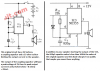
The 100 ohm resistor and the 10 uF capacitor provide better decoupling of the power supply to the 4017. You may have to take steps like this when it is fitted to the car / van (I assume it is for an ice cream van.) I do not know how the start button can work at all the way you have it connected in your schematic in the .jpg file Why did you change from the way I showed it connected ? I am not convinced you have it connected in either the way shown in your diagram or my diagram.

Les.
 
Sorry, made mistake when drawing, 10n cap. should connect the pin 15 after the Sw. as shown in coreected drawing.
checked and,was connected correctly on test breadboard. Any suggestion for suitable IC to replace Astable Osc. Cct ?
Attached 555 Osc. Cct produces both triangle and square waves..but I need Sinewave to produce sound of set notes.
Found good tutorials on Utube for Eagle Software, hoping you will see my terrible drawings cured when I figure out how to use it.. Thanks.
 

Attachments

  • SW Correction.jpg
    SW Correction.jpg
    810.6 KB · Views: 430
  • SW Correction.jpg
    SW Correction.jpg
    810.6 KB · Views: 330
  • VCO-dig[1].png
    VCO-dig[1].png
    19.9 KB · Views: 316
Why are you SHORTING the output of the 555 with an 8 ohm speaker? It is probably destroyed now. Its output will try to go up to 9.5V then its output current will be 9.5V/8 ohms= 1190mA but its maximum allowed output current is only 200mA.
What is the diode for? Why is the capacitor value so small?
 

Attachments

  • melody maker.png
    melody maker.png
    99.1 KB · Views: 245
I am not using, just copied and pasted from web. to show you it did not work. also take a look attached similar circuit
speaker is driven by Transistor. still does not make sense to me, since 4017 summed output is directly connected to output (pin.3) of 555 should I try this instead Astable Cct ? I corrected the Push Sw. connections in previous drawing.
 

Attachments

  • 555-4017-555.gif
    555-4017-555.gif
    8.5 KB · Views: 1,394
If the push button is wired as in my diagram (And your corrected diagram.) the only way I can see that the 4017 sees a rested when the button is held down is it there is a spike on the supply line. You could try putting a 10K resistor between the push button and the 12 volt supply and a 10 uF capacitor between the junction of the 10K resistor and the push button (+ end of capacitor) and the negative of the capacitor to 0 volts. The only other oscillator chip I can think of is the ICL8083 but I think it is obsolete.

Les.
 
Ok. I will do your suggested modification, also try 555 output config. in diagram, which asked your opinion. will let you know the results. when finalized and boxed, will use in my car to play the pre-setted tune, don't have in ice-cream truck. : ) * they play much longer continous tunes..of different melodies recorded in a chipped box available on Ebay.
Thanks.. TeknoFix.
 

Attachments

  • 555-4017-555.gif
    555-4017-555.gif
    8.5 KB · Views: 309
The tone generator 555 (IC2) Will generate a tone whose frequency in mainly determined by the values of C2 and R2 The resistors selected by the 4017 will have a very small effect on the frequency. (But I don't think it will be enough to give the range of frequencies that you want.) The voltage to the top of R2 is switched by the output of the 555 instead of the discharge transistor and it's collector load resistor. This should give an output square wave with a mark space ratio closer to 50% than if the discharge transistor is used. The output transistor will give more drive to the speaker than if it was driven directly from the 555 output. I think an error was made when the circuit was drawn. I think the junction of R3 to R10 was intended to go to the bottom of R2 rather than the top. Connected like that the outputs from the 4017 would have a greater effect on the frequency. (It will also change the mark space ratio of the output square wave away from 50%)

Les.
 
Status
Not open for further replies.

Latest threads

New Articles From Microcontroller Tips

Back
Top