Hi every one,
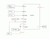
i want to monitor the health status of 24V battery using LM3914 IC, i am new to this type of work, what my doubt is can we monitor the 24V battery health status using this IC , can any one please explain how it will work and how many ICs i need for this requirement,thanks in advance.
i want to monitor the health status of 24V battery using LM3914 IC, i am new to this type of work, what my doubt is can we monitor the 24V battery health status using this IC , can any one please explain how it will work and how many ICs i need for this requirement,thanks in advance.
")