Electro Tech is an online community (with over 170,000 members) who enjoy talking about and building electronic circuits, projects and gadgets. To participate you need to register. Registration is free. Click here to register now.
Welcome to our site! Electro Tech is an online community (with over 170,000 members) who enjoy talking about and building electronic circuits, projects and gadgets. To participate you need to register. Registration is free. Click here to register now.
Hi,
in battery monitoring(in addition to LM3914) we need to blink an LED which will indiacte battery needs charging.is it possible to do this with LM3914 or is there any other simple solution.
Hi,
in battery monitoring(in addition to LM3914) we need to blink an LED which will indiacte battery needs charging.is it possible to do this with LM3914 or is there any other simple solution.
i am having LED bar which will monitor the LED status from 10V to 15V below 10V all LEDs in BAR are turned off , then i need to blink an LED which will indicate battery needs charging immediately.how we can achieve this with LM3914 IC.
i am having LED bar which will monitor the LED status from 10V to 15V below 10V all LEDs in BAR are turned off , then i need to blink an LED which will indicate battery needs charging immediately.how we can achieve this with LM3914 IC.
OK.
I will post a led flasher circuit using one of those opa's
EDIT:
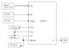
This option is using a 741 opa.
The remote LED will flash at approx 2 hZ, when LED#1 [pin1 of the LM3914] is OFF, ie: not LIT.
If you want the flash to occur at different LM3914 LED off, move the detection circuit to the required LM3914 LED.
thank you sir, but i have one doubt in the circuit LM741 7 pin is connected to +v pin and 4 pin is grounded but in real time when i am grounding the 4 pin in LM741 is not giving the required result for any circuit.
thank you sir, but i have one doubt in the circuit LM741 7 pin is connected to +v pin and 4 pin is grounded but in real time when i am grounding the 4 pin in LM741 is not giving the required result for any circuit.
can somebody help me to work out the programing part for this project which is used LM3914. I really don't know how to work it out. Together with this post, I attached the brief explanation about my project.I really hope somebody will help me to work it out.Thank You..
The LM3914 does not have anything to program. R2 and R3 are simply calculated to make a DC reference voltage so that the 10th LED lights when the peak input voltage reaches this voltage and also determine the current in the LEDs for brightness. Just copy the circuit and build it.
The rectifier D2 and the filter capacitor C3 are not needed.
my lecturer asks me to run this project by using the computer software first..because of that i really need the coding in order to run the project...but I don't know how to make the coding.. I really hope that somebody will help me...
If you read the datasheet for the LM3914 then you will see that it is simply a voltmeter and has nothing to program and does not use coding.
Its block diagram shows that it is completely linear and has no digital logic, no microcontroller and no memory.
I do not know what "computer software" your lecturer is talking about. Maybe it is a Spice simulation program that has a model of the LM3914.
I don't know if a model is available. The model will be a list of codes.
But the LM3914 is so simple that a simulation is not needed since it is just a voltmeter.
Thank you very much sir for your help.I will try my best to do this project although I didn't have enough experience. I will refer to you again if I have any doubt after this. Thanks again.
sorry sir my proteus is not properly installed thats why i am unable to post the circuit, i have drawn the circuit in word, please see this and tell me where i am doing wrong
Hi. Personally I prefer using PNG images. DOC files is slow, space hogs, and also not everybody is able to read (or simply doesn't bother opening their sloooowwww office program).
On the other hand, saving as PNG picture doesn't take much of an effort. Virtually any image viewers can "grab" the content of the sceen and save it. My personal favorite program is FSIV. Saving your picture as a black/white PNG image looks like this:
[edit]
Also, while Im on the task about to teach you some practical things about files: By using a program such as Inkscape you WILL be able to produce drawings that looks much more pretty than they do if you use ms word.
[edit 2]
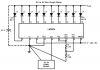
I got a correct drawin - straight from the datasheet. You can compare and make any corrections:
This site uses cookies to help personalise content, tailor your experience and to keep you logged in if you register.
By continuing to use this site, you are consenting to our use of cookies.