Continue to Site

Welcome to our site!

Electro Tech is an online community (with over 170,000 members) who enjoy talking about and building electronic circuits, projects and gadgets. To participate you need to register. Registration is free. Click here to register now.

  • Welcome to our site! Electro Tech is an online community (with over 170,000 members) who enjoy talking about and building electronic circuits, projects and gadgets. To participate you need to register. Registration is free. Click here to register now.

Help Increasing Time Delay on Motion Sensing Camera

Status
Not open for further replies.
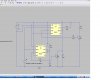
Sorry if the 12.2kΩ between Pin2 and Pin8 was intended, all OK. I'm more familiar with higher voltages in AC so it seemed like a low resistance to me ;)

Also, my mistake, I did mean removing the R1 resistor.

I think we only have 3 input/output voltages to consider, and in two states, no motion and motion so I'll give you all of those readings in future posts which should help debug. The battery needs a recharge but all is functioning.

Gnd + Pin2 (trigger)
No Motion = 3.79v
Motion = 3.8v blip then 3.79v to 3.78 (this should be roughly zero volts)

Gnd + Delayed Output
No Motion = 3.82v
Motion = 3.83v

Gnd + Pin8 (Vcc)
No Motion = 3.82v
Motion = 3.83v


With No Motion Gnd + Pin2 = 3.79v
Grounding Pin2 starts recording,
with jumper connecting Gnd + Pin2 = 0.02v
with jumper removed still recording for timed period
Gnd + Pin2 = 3.73v
then back up to 3.79v when timed period ends.


I hope that helps to shed a little light on the problem Brownout.
 
I could never have imagined that any product would have such a pathetic output that it couldn't drive 10K ohms. That's frustrating. The only solution I can think of is to replace the first two transistors in the chain with an operational amplifier, that has hundred's of Kohms of input resistance. Unless someone has a better idea, I'll gin up and post a drawing later today.

EDIT: Do you realize that the output current requirement is only 320 micro amps? I can hardly believe your sensor can't drive that much. We'll look at a different solution for the transistors if you like. Probably shouldn't have used transistors in the first place.
 
Last edited:
I figured it was nearly there after the early success. :(

Is the problem with the last circuit anything do with the resitance on the output, ie 39KΩ up to 5MΩ (+39KΩ)? I haven't changed that part of the circuit at all.

I'm thinking it might need something like a relay, e.g. no voltage present, holds relay down and is locked down until timer releases the relay.
 
Please make sure it's wried correctly. In the meantime, I'll work up a drawing that uses a high input impeadance op-amp in place of the transistors.
 
Here's something else to try. I used a second 555 timer, because if you sensor can drive one, it should be able to drive 2. You can get a dual 555 in a single package, it's a 556. The 2nd timer is set to produce a short discharge pulse to start the time cycle over for each pulse received from the sensor.

I would have suggested something like this from the beginning, but I didn't anticipate the problems with our simpler drivers. Live and learn.

PS: Before you go to the trouble to build yet another circuit, it might be a good idea to measure the output capacity of your sensor. You'll probably need an oscilloscipe to do this. Beg, borrow or steal one. This is the way engineering should be done. Guessing sucks, as you have learned.
 

Attachments

  • retrig7.JPG
    retrig7.JPG
    90.4 KB · Views: 153
Last edited:
You can get a dual 555 in a single package, it's a 556.
.....
I would have suggested something like this from the beginning, but I didn't anticipate the problems with our simpler drivers. Live and learn.
.....
PS: Before you go to the trouble to build yet another circuit, it might be a good idea to measure the output capacity of your sensor.

The 556 always struck me as the more elegant solution to this problem, I hope it works. I'm a keen advocate of live and learn, so no problem for me :)


Output Capacity? is that amps or watts or another measure?

I doubt if I'll be able to borrow a scope, but I can measure down to 200µA on my cheapo multi-meter.

I'm away for a week but looking forward to getting the 556 and other parts to test this out, thanks again for sticking with it BrownOut.
 
The problem with your cheapo multi-meter is that it won't be fast enough to capture a fast output pulse. Even expensive multi-meters are slow as Christmas. If you try the 556 and still can't get it to work I'd suggest you mail the sensor to me, and I'll send it back with a diagram which will be gaurenteed to work. It's starting to piss me off that I can't get this right. :)
 
It works!!!

If you try the 556 and still can't get it to work I'd suggest you mail the sensor to me, and I'll send it back with a diagram which will be guaranteed to work. It's starting to piss me off that I can't get this right. :)

No need... the latest circuit does work.... YAY!!!!!! :D

I used two 555 timers but it works brilliantly.. very many thanks and thanks for your time and patience.

Let me know if you received my PM on possibly making a few of these units Brownout for $$$$.. the PM doesn't appear to have been sent.

Fantastic.. I am so chuffed :)
 
Inscrutible Chinese design baffles me

I'm very happy this is working.

So was I.. BUT............. NO I've been thwarted!!! :mad:

While I was testing it I noticed an inconsistancy in the commence recording cycle, for some reason best known to the manufacturer/designers if the LCD display goes into standby, then it ignores the first motion input, and simply turns the LCD display back on awaiting another motion trigger before it starts recording!!

This isn't so much an issue when it will accept a new trigger every second or so, but once the timeout is triggered it won't accept a new trigger untill motion is no longer sensed and the timer has completed it's cycle. Then it will commence recording if it is re-triggered.

The LCD display has 3 settings..
1. Turn off after 1 minute
2. Turn off after 5 minutes
3. Never turn off

The only workaround I can think of is to set the display to "3. Never turn off" then somehow disable the display manually to save power. (sadly it's not an option to leave the display on permanently, as it drains the battery fairly rapidly in normal use.)

I'm totally gutted the dual timer circuit worked great, and then to be hit with that glitch was totally unexpected.

I doubt if this will be a simple "put a series switch in a cable to the LCD display" fix, but I'll give it a go, I'm not one to give up at the first hurdle.


Gutted :(
 
Never say die!!!!

I don't think putting a manual switch on the LCD display is going to work, I did take the DVR apart but as you can see from the photos, it's the usual ribbon/tape connection to the display, which I would destroy if I put a soldering iron anywhere near it!!


I think there is an electronic circuit solution to this problem, now I've had time to think about it.

Initial trigger takes unit out of standby mode, additional triggers start recording.

The additional trigger we have already sussed using the dual timer.

But I need to start recording on the initial trigger.

So what is needed is a start/stop pulse to take the DVR out of standby to prepare it for the subsequent trigger recording sequence.

I figure as a signal it would look like 0v (approx 1 second) 3.8v (approx 1 second) then 0v from the dual timer circuit until motion sensed/delay is completed. Which I guess would call for yet another 555 timer!!!

Then the next motion to trigger after everything finishes recording would need to commence back at the 0v to 3.8v then dual timer sequence.

If you need me to explain that more clearly, feel free to ask BrownOut.

I think it's with persevering having come this far!!

Attached are the photos of the internals.. right before I took a lump hammer to the whole thing :mad:
 

Attachments

  • JS309M_pcb01s.JPG
    JS309M_pcb01s.JPG
    134.1 KB · Views: 172
  • JS309M_pcb02s.JPG
    JS309M_pcb02s.JPG
    280.6 KB · Views: 158
  • JS309M_pcb04s.JPG
    JS309M_pcb04s.JPG
    394.4 KB · Views: 160
  • JS309M_pcb05s.JPG
    JS309M_pcb05s.JPG
    196.9 KB · Views: 157
If I understand the issue, there should be an easy solution without another timer. All it needed is a short "wake up" pulse. We can simply hold off the timer for a few mS while we pass the signal straight from the detector to the recorder. The detector signal wakes up the recorder, then the timer signal kicks in a few mS later to start the recording process. What do you think?
 
If I understand the issue, there should be an easy solution without another timer. All it needed is a short "wake up" pulse. We can simply hold off the timer for a few mS while we pass the signal straight from the detector to the recorder. The detector signal wakes up the recorder, then the timer signal kicks in a few mS later to start the recording process. What do you think?

Sounds about right BrownOut, the "wake up" pulse being down to zero volts then back up to 3.8v then back down to zero volts from the timer signal.

I'm not sure how long those pulses should be, but mS sounds about right.

Is there a widget that does that? ;)
 
Here's what I'm working on. Look at the waveform. The pulse triggers the circuit at 1 second. The output is a short pulse followed by sustaned low level. The initial pulse wakes up the recorder (hopefully) and the sustained level controls the recording. There are 3 critical timing nets that control the pulses. First, R1 and C3 delay the triggering of U1 to allow time to send the wake up pulse. Second, R3 and C2 ensure there is enough time for the delay and the subsequent trigger for U1. Last, C4 and R4 terminates the wake up pulse in time for the output to return to a high level, before U1 fires. Please study the circuit and let me know if there is anything that isn't clear. It may be required that the 3 timing nets by "tweaked" to get the pulses correct for your recorder. We can streach or shrink each of these pulses as required.

I have more testing to do on this circuit before you try it. I'll continue testing and let you know when I have confidence.
 

Attachments

  • retrig8.jpg
    retrig8.jpg
    125.5 KB · Views: 158
Looking good, my main concern was the 5mS pulses in the waveform shown maybe too short.

I've tried to test this by manually "dabbing" connections to replicate a trigger by removing the output (Collector Q3 NPN transistor) in this sequence ON OFF ON OFF as fast as I could and that did successfully wake the DVR and then start recording, so now I'm reasonably confident fairly short pulses should do the trick.

I'm looking forward to testing the new circuit :)
 
Last edited:
Well, at least all the timing nets can be scaled together. Here is a modified pulse of about 50 mS, uning linear scaling of the 3 time nets discussed above. Still testing...

EDIT: We might want to replace the diodes and output transistor with integrated gates. You might have to lose your resistance to them. :)
 

Attachments

  • retrig8_1.JPG
    retrig8_1.JPG
    129.2 KB · Views: 157
Last edited:
Final Version

Here is the final version, fully tested. I made one small change from the previous one. I wish I had time to breadboard this, becuase some of the timing is a little tricky. If you can't get this to work, I'll make some time to build and test the "real" circuit.

EDIT: You may change R1 and C3 to 10K and 47u respectively if you wish, just to make part ordering easier.

I hope only one wakeup pulse is needed; otherwise, we're screwed.
 

Attachments

  • retrig8_1.JPG
    retrig8_1.JPG
    129.3 KB · Views: 152
Last edited:
Here is the final version, fully tested. I made one small change from the previous one.

I figure the only change is C2 = 47µF in the second version?

I hope only one wakeup pulse is needed; otherwise, we're screwed.

If you mean one wakeup pulse cycle.. ie Standby 3v.. 0v Wakeup Pulse.. 3v Standby.. 0v Record Pulse, then that will do, but there may be several recording sessions each one requiring a wakeup cycle.


I shall get the parts and test it, there's very little point in you getting the parts without a DVR, although if you did buy one and we did get this fix to work then I'm fairly confident I could find someone to buy the "fixed" unit from you if you put it on Ebay.

Let me know if you want to get one and I'll make sure you get the right unit.

Thanks again for sticking with it BrownOut :)
 
You go boy! I only thought it would be good to 'scope the output to ensure the simulator is giving me the correct result. Yeah, it's good to validate these things from time to time. You have the actual recorder, and I have the 'scope. If I get time, I'll see if I can make a quickie, but there are alot of projects on my bench right now. Hopefulle, you'll get it to work, and I won't need to do anything else :)

BTW, I am interested in motion detection, and I have a couple MD projects going on right now. I might get the gear and make one for myself, or for resell on e-bay. Not sure quite yet.
 
Last edited:
Status
Not open for further replies.

Latest threads

New Articles From Microcontroller Tips

Back
Top