Continue to Site

Welcome to our site!

Electro Tech is an online community (with over 170,000 members) who enjoy talking about and building electronic circuits, projects and gadgets. To participate you need to register. Registration is free. Click here to register now.

  • Welcome to our site! Electro Tech is an online community (with over 170,000 members) who enjoy talking about and building electronic circuits, projects and gadgets. To participate you need to register. Registration is free. Click here to register now.

help Feedback winding for resonance with pll 4046

Status
Not open for further replies.

sebosfato

New Member
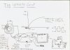
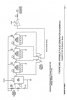
Hello i need help to finish my design of my resonant transformer it is able to multiply the voltage in by a factor of at least 100 with few windings. I'm working on a pll design that needs to be able to tune automatically to the resonance of two in one tank circuits, one parallel and one in series, formed between inductors stray capacitance and inductance and also in series with the second capacitor and one of the inductors. The point is that i need to design a feedback coil that get the resonance frequency signal and transform it to 50% duty cycle square wave to use it to lock the 4046.
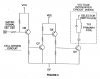
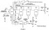
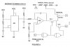
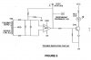
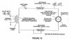
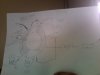
I need help thus with the figure 9,8, and 7. Figure 7 is the pll 4006 i think on the left and 4001 on the lower part this part of the circuit i have already working-+, Figure 9 is the feedback signal it needs an op amp i don't know witch. and resistors value. i bough a lm393 tried to wire like that and didn't work i used 500 ohms on the feedback prior to diodes and resistors value i tried with 50k 1k here and there. hope some one can help me please. This circuit is made for extract electrons from the air and reuse them as a source of energy by creating a second even higher voltage connected in series with it thus a flow for that available current source.

Thank you
 

Attachments

  • wo92-5.jpg
    wo92-5.jpg
    30.6 KB · Views: 1,813
  • wo92-7.jpg
    wo92-7.jpg
    54.6 KB · Views: 2,058
  • wo92-8.jpg
    wo92-8.jpg
    37.3 KB · Views: 2,362
  • wo92-9.jpg
    wo92-9.jpg
    31 KB · Views: 3,417
  • wo92-10.jpg
    wo92-10.jpg
    47.2 KB · Views: 1,624
  • Instantânea 2009-05-15 16-59-28.jpg
    Instantânea 2009-05-15 16-59-28.jpg
    89.1 KB · Views: 1,320
Last edited:
the resonant tansformer

This is the transformer I made it has 200 turns of 24awg for the primary witch are wounded over the secondary witch have 600 turns of 36awg and than respecting the same direction are wounded a bifilar fashion the inductors 100 turns of 24awg wire. These are connected as you see in the picture.

The voltage should be 60 volts and the max voltage will be this if you don't use the exact configuration I draw, for example if you invert the diode it will not work and will show only 60 volts.

When secondary is subjected to a pulse and by the action of the diode that don't allow for the capacitor connected to discharge, the inductors connected after the diode being subjected by the same pulse makes another pulse that adds the first, this way voltage goes up to and beyond 100x the input voltage. From 12v it generate more than 1200 volts and from 220 it puts out more than 30kv. With few turns.

It already works without the resonance condition. The inventor called them resonance charging inductors as you see in the figures. I think if i make them to resonate in parallel with each other like i described in the first post im going to have a very high voltage and at the same time max impedance so it wont allow current to flow.

The strange thing is that all i did to discover how is it made, was understand and work on the directions of current flow. i was trying to construct it for more than 2 years but by lack of knowledge was not possible. Now its very clear to me the step charging effect.

Please i need some help on the feedback ad pll design.
 

Attachments

  • Foto63.jpg
    Foto63.jpg
    53.7 KB · Views: 1,111
Please some help? i think the diagram 8 the resonance scanning circuit is a 555 timer with a comparator that shorts when it reach the predetermined voltage, making a ramp oscillator, its signal goes to the pin 9 of 4046 but is controlled by the lock signal (4001) to stop when it is in lock. What are that transistors? and possible opamp for that? Please any help would be great
 
Any help would be great.

I'm trying another circuit with the 4046 but when i turn it on it burns do you know why does it happen? here the schematics.
 

Attachments

  • selfreso-schematic.gif
    selfreso-schematic.gif
    26.1 KB · Views: 4,027
Any help would be great.

I'm trying another circuit with the 4046 but when i turn it on it burns do you know why does it happen? here the schematics.

Solved you must connect pin 7 and 14 of 4001 ic to ground and vcc respectively, and the 4046 must be connected 16 positive 8 ground and pin 5 tru 10kohm resistor to logic hi. i'll still improving it news soon.


Please help me with the other schematics if you can anything about the op amps used would be great.
 
I guess not.

JimB
 
If no one helps as soon as I can I'm going to figure out all the components and continue this thread. Jim tanks for presence.
And that is true about experience hehe all i learned was frying my components :) and multimeters haha
 
Sebosfato;

What do you mean by the following statement:

"This circuit is made for extract electrons from the air and reuse them as a source of energy by creating a second even higher voltage connected in series with it thus a flow for that available current source. "
 
Last edited:
Any help would be great.

I'm trying another circuit with the 4046 but when i turn it on it burns do you know why does it happen? here the schematics.

Sebosfato;

Won't go into all the errors I found, way too many.

But will provide a sample: on the CD4046 circuit you have connected the signal input, but the phase comparator input is grounded, and the VCO is disabled. That circuit is doing absolutely nothing at all. Also, if it is burning, it is because the signal input is sky-high.
 
Last edited:
This circuit is made for extract electrons from the air and reuse them as a source of energy by creating a second even higher voltage connected in series with it thus a flow for that available current source.

Really :rolleyes: are you trying to build an overunity power generator?
 
hi fernando,

That was a different schematic that uses the pll as a very sensitive signal input , it was frying because it needs a 10kohm resistor between pin 5 and positive side and pin 16 and 8 connected to respectively to positive and ground.


About the electron extraction circuit I calculated that in 1/2 mole of oxygen if you ionize it taking off 4 electrons per atom you have 100 amps of current. Its all about to find a way to use this free electrons to do whatever we want. After I discovered this I made some research and I found Bruce Perreault work that just confirm exactly what i was thinking. So is all about find a way to use this huge source of amps. Seems impossible but even conservation of energy allow this condition just because it is not a close circuit. Energy must come from somewhere no?, it comes from the electrons in the atoms. Obviously you need energy to tap to this energy source i believe is much less than we can put out of it.

Think about the alternator, don't you have to put a small energy for it to work? Just the same happens here but we are using HV to be able to do so.
Thanks for the reply.
:)
 

Attachments

  • Instantânea 2009-05-21 08-55-15.jpg
    Instantânea 2009-05-21 08-55-15.jpg
    51.2 KB · Views: 728
Really :rolleyes: are you trying to build an overunity power generator?

Yes it must be over unity. By two high voltages i mean that i use about 40kv to ionize the air and them i create more 500v or more in series but a different circuit being able to create a path to that electrons to go. I designed an schematic i called the Infinity Circuit. There are two resonant transformers connected the positive of one on the negative of the other and a diode between the other positive side and the negative of the first the transformer is like the one i showed in the previous post, drive in resonance to have a very high impedance path allowing to the current to flow where and when i want it to flow.

I posted here because i need help with the electronics to do such thing. On over unity forums generally every one says what think and aways not related with what you need to know. Maybe i'll create a thread there also.
Thanks
 

Attachments

  • TheInfinitycircuit.jpg
    TheInfinitycircuit.jpg
    2 MB · Views: 957
Last edited:
Scam scam scam scam, doesn't work, never will.

Like I said overunity.com will offer hugs and won't discourage overunity money pits.

Since you may have missed it I'll post the link again.
**broken link removed**
 
Scam scam scam scam, doesn't work, never will.

Like I said overunity.com will offer hugs and won't discourage overunity money pits.

Since you may have missed it I'll post the link again.
**broken link removed**

I know people think Bruce Perreault and Stanley Meyers are scam i don't care very much about that i would like to discuss here the electronics to have a Phase locked loop, with a resonant scanning circuit, a feedback, and phase lock indicator, as i shown on the first post. I'm going to try these theory I created so if you did't tried yet please don't say it is a scam because you are not sure. I would like but i don't want your money or anything, all i want is to discuss about electronics.

I discovered that on the resonant scanning circuit figure 8 A31 is a 555 timer and Q14 and Q15 should be Jfet mosfets that are normally on. The logic gates down are nor gates 4001 used as not gates.

Bruce paper that i think confirmed what i was thinking. https://www.electro-tech-online.com/custompdfs/2009/05/patent.pdf

Thanks
 
Last edited:
Actually, isn't the government funding cold fusion experiments again?
By the way sebos, if your project works I'll empty my bank account and give it to you, because the entire world economy will collapse over night.
 
Last edited:
Anyone can get a Patent, the patent office doesn't care if they work or not.

That is true but i insist studying about that because i knew some one that really had problems with gov because invented a water car like and other of his inventions so i'm sure conspiracy exist is not theory and as such i know that this technology exists and we just have to find the right way to get there i'm studying about this since 3 years ago and i didn't studied electronics the classical way all i learned i learned by myself reading on wiki google books Physics, Chemistry, Mathematics, until i knew mit open course witch i followed enough to understand what i still need to understand. sorry about my english i'm brazilian. k

I'm doing this because i believe is the only key to a better world.
 
Status
Not open for further replies.

Latest threads

New Articles From Microcontroller Tips

Back
Top