windozeuser
Member
I have about 32 seconds worth of accelerometer data of a basic driving scenario 25MPH normal roads along with hitting about 7 potholes and a rough patch of road. The accelerometer is mounted on the dash board of my car with double sided tape.
Problem: I have all the data that is noisy from the accelerometer, and I need to make a simple way to detect that a pothole event has occurred. Below are several graphs of data in time domain and FFT. The accelerometer is measuring in GForce
Basically I want my arduino to know a pothole has occurred with fairly great accuracy and not using graduate level mathematics and techniques.
Accelerometer sampled at 100hz has a simple 50HZ RC LOW PASS FILTER ON THE Z AXIS
Here is the CSV data for the 32 seconds of accelerometer readings TIME, GFORCE format:
https://textuploader.com/?p=6&id=sQlb
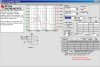
Black trace is RAW unfiltered Accelerometer data:
Blue trace is filtered by a bandstop filter based on the extreme frequencies found in FFT, Dominate 2HZ and 12HZ.
**broken link removed**
Pothole event looks like this in time domain:
**broken link removed**
not sure what the 10 to 15HZ component is in the FFT, is that the actual pothole, or is it the wheel hop of the wheels against the road, or is it the resonant frequency of the car?
FFT:
**broken link removed**
seems like it is the actual pothole events, here is a HPF @ 13HZ The dominant features of the potholes seem enhanced
**broken link removed**
I want to be able to detect and count the potholes in real time
It seems to be counter-intuitive the suspension should move a lot slower than a 10 to 13 HZ that would cause motion-sickness I believe
UPDATE:
As per friends suggestions, I used the full bandwidth of the accelerometer 1000HZ and the maximum sampling rate I could get on the arduino.
FFT:
FFT UNFILTERED DATA FULL BANDWIDTH of ACCELEROMETER:
**broken link removed**
here is a sample piece of data of the pothole event and some bumps and road noise around it:
UNFILTERED DATA POTHOLE EVENT
**broken link removed**
Added the Diode envelope detector circuit, output looks the same... The accelerometer always output 0 to 3.3Volts not negative... I based this idea on filtering and holding the amplitude of the signal like in radio, but the sensor doesn't go negative voltage. the output didn't change much at all. I picked the RC time constant to be around 2mS, I'm sampling at 2mS 500 Samples/ second The accelerometer voltage is always between 0 and 3.3V though... never goes negative so the diode wouldn't work?
**broken link removed**
I did not see a HUGE different in increasing the sampling from 100HZ to 500HZ, the signals looks almost the same. Also, the FFT suggests anything over 55HZ or so can be cutoff, the pothole event would be a high frequency event though kinda like a step input? I'm not sure how I can reliably filter and detect the peaks of the pothole event form the surrounding road noise
Problem: I have all the data that is noisy from the accelerometer, and I need to make a simple way to detect that a pothole event has occurred. Below are several graphs of data in time domain and FFT. The accelerometer is measuring in GForce
Basically I want my arduino to know a pothole has occurred with fairly great accuracy and not using graduate level mathematics and techniques.
Accelerometer sampled at 100hz has a simple 50HZ RC LOW PASS FILTER ON THE Z AXIS
Here is the CSV data for the 32 seconds of accelerometer readings TIME, GFORCE format:
https://textuploader.com/?p=6&id=sQlb
Black trace is RAW unfiltered Accelerometer data:
Blue trace is filtered by a bandstop filter based on the extreme frequencies found in FFT, Dominate 2HZ and 12HZ.
**broken link removed**
Pothole event looks like this in time domain:
**broken link removed**
not sure what the 10 to 15HZ component is in the FFT, is that the actual pothole, or is it the wheel hop of the wheels against the road, or is it the resonant frequency of the car?
FFT:
**broken link removed**
seems like it is the actual pothole events, here is a HPF @ 13HZ The dominant features of the potholes seem enhanced
**broken link removed**
I want to be able to detect and count the potholes in real time
It seems to be counter-intuitive the suspension should move a lot slower than a 10 to 13 HZ that would cause motion-sickness I believe
UPDATE:
As per friends suggestions, I used the full bandwidth of the accelerometer 1000HZ and the maximum sampling rate I could get on the arduino.
FFT:
FFT UNFILTERED DATA FULL BANDWIDTH of ACCELEROMETER:
**broken link removed**
here is a sample piece of data of the pothole event and some bumps and road noise around it:
UNFILTERED DATA POTHOLE EVENT
**broken link removed**
Added the Diode envelope detector circuit, output looks the same... The accelerometer always output 0 to 3.3Volts not negative... I based this idea on filtering and holding the amplitude of the signal like in radio, but the sensor doesn't go negative voltage. the output didn't change much at all. I picked the RC time constant to be around 2mS, I'm sampling at 2mS 500 Samples/ second The accelerometer voltage is always between 0 and 3.3V though... never goes negative so the diode wouldn't work?
**broken link removed**
I did not see a HUGE different in increasing the sampling from 100HZ to 500HZ, the signals looks almost the same. Also, the FFT suggests anything over 55HZ or so can be cutoff, the pothole event would be a high frequency event though kinda like a step input? I'm not sure how I can reliably filter and detect the peaks of the pothole event form the surrounding road noise
Last edited: