Continue to Site

Welcome to our site!

Electro Tech is an online community (with over 170,000 members) who enjoy talking about and building electronic circuits, projects and gadgets. To participate you need to register. Registration is free. Click here to register now.

  • Welcome to our site! Electro Tech is an online community (with over 170,000 members) who enjoy talking about and building electronic circuits, projects and gadgets. To participate you need to register. Registration is free. Click here to register now.

Help and advice on filtering accelerometer data from pothole event

Status
Not open for further replies.
C5 and C6 block any dc component that might be riding on the Wav input. U1 is a (gain of 1) voltage follower for an offset applied to the non-inverting input, so the voltage divider R6-R7 biases that to 2.5V.
 
So the Caps block the 0HZ component of the signal, the output of the accelerometer is DC but it's changing at higher frequency and will still go through, correct?
 
So the Caps block the 0HZ component of the signal, the output of the accelerometer is DC but it's changing at higher frequency and will still go through, correct?

Yes. Here is a 1Vp-p signal riding on a 3V offset which turns on at 1s and turns off at 2s. Note how the 1V sine wave centers itself around 0V after C1 charges/discharges. How long that takes is determined by the time constant C1*R3.
 

Attachments

  • D2b.jpg
    D2b.jpg
    200 KB · Views: 170
Last edited:
I have some lm324s it appears they would work ?

Found a TLC272CP

And found an AD620 in my supply parts too

ugh I have 50 741's haha
 
Last edited:
LM324s have a common mode input range that includes Vss; their output will pull quite close to Vss, but they suck at pulling their output pin near Vdd. Look at the data sheets on the others to check how close the output pin will swing to Vss and Vdd. The input common-mode range should be from Vss to at least 1v below Vdd. If you want single supply operation, then you gotta use the right opamps.
 
Thanks mike for all your help, really appreciate your effort and time. I ordered some opamps they are comming in a few days

I was wondering what bandwidth you used for the bandpass filter lower and higher corner frequencies,

I manged to replicate your results within labview, but not as great as yours, the "noise" is pretty high still, Labview doesn't have an envelope detector, would an equivalent be RMS or average?

**broken link removed**
 
Here is a Bode plot of both filters. I use some free software from Texas Instruments to synthesize the filters.
 

Attachments

  • W2as.jpg
    W2as.jpg
    151.2 KB · Views: 162
  • W2ap.jpg
    W2ap.jpg
    374.7 KB · Views: 152
Looks like -3DB points are @ 10HZ for lower corner and 23HZ or am I reading it wrong lol?

-40dB roll off so 2nd order filter
 
Looks like -3DB points are @ 10HZ for lower corner and 23HZ or am I reading it wrong lol?

-40dB roll off so 2nd order filter

It is a narrow bandpass with gain. Gain at 12.36Hz is 14db. Down -6db at 10.45Hz and 14.82Hz. Down -20db at 5.16Hz and 30.03Hz, relative to the peak.
 
I ordered some MCP601 Opamps, https://www.electro-tech-online.com/custompdfs/2013/02/21314g.pdf

built the bandpass filter, but I can't get a signal on the output. I'm thinking its because the accelerometer never has a negative voltage its DC, and the caps are blocking the signal. So I would have to zero the accelerometer with another opamp to make it go +2.5V to -2.5V output to make the bandpass filter work?

The accelerometer reads low positive voltages below VCC/2 as negative G's

**broken link removed**
 
Ok sweeping the bandpass filter, it seems to be operating in reverse, frequencies around 7 to 15HZ are severely attenuated and then high frequencies 100HZ to 1KHZ the amplitude shoots up more and more to almost VCC o_O
 
The filter simulation drives the input of the filter with a voltage source. Could be that the accelerometer output is high impedance. Try a voltage-follower OpAmp between the accelerometer and the input of the filter.
 
Ah theres a 32K resistor built in the output of the accelerometer so I removed the 34K resistor and directly connected the accelerometer output

No luck...

Also I'm using a signal generator with 50 ohm impedance (adjustable 50ohm or 600ohm switch) sweeping different frequencies into the input of the 34K resistor input to the differential input of the opamp

would I still need the buffer (voltage follower) for both tests?


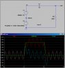
seems like its acting like a bandstop filter, lowest amplitude where it should be largest, and outside frequencies get amplified


The simulation in both MultiSIM and LTSPice works correctly though o_O

seems to be the 330nF ceramnic capacitors I used o_O When I use Ceramic caps, it doesn't work, it works opposite has a band stop filter and amplifies higher frequences, if I use tantulum capacitors it works CORRECTLY, but they are polarized, and also drift the signal as they charge and discharge

What caps should I be using, and why does ceramic caps not work?
 
Last edited:
been following this thread and found it very intresting, so anyway the signal from acclerometer has been processed by hardware to make the potholes more clear, would you call the is analog signal processing, if so could the same process been done using dsp, i think using op amps is better though as cheaper and dsp implemention is more expensive, am i correct or wrong. anyway i love the process you to have been through and solutions are great thanks for posting all this.
 
Yes it can be done in DSP, FIR filters, and any type of filter could be implemented, if you load the Raw signal into a program like Matlab or Labview you can filter it using DSP methods. However, DSP I'm a total newb at haha.

In labview earlier I simulated all the results that Mike did in LTspice, getting the circuit to work in real life with real components though seems to be the real challenge haha

I'm gonna be posting my results with the bandpass filter, mike... It's mind boggling to me, its operating as a bandstop filter, but in simulation is behaves as a bandpas o_O. If I use the tantulum capacitors it actually works correctly, but they are polarized and also cause the signal to charge up over the time constants of the capacitor, the signal moves from 2.5volts in steps you can actually see the signal moving higher and higher because the capacitor is charging little by little.

the ceramic caps However, cause it to attenuate at the frequencies it should be amplifying at..
 
Last edited:
been following this thread and found it very intresting, so anyway the signal from acclerometer has been processed by hardware to make the potholes more clear, would you call the is analog signal processing, if so could the same process been done using dsp, i think using op amps is better though as cheaper and dsp implemention is more expensive, am i correct or wrong. anyway i love the process you to have been through and solutions are great thanks for posting all this.
The filter posted above consists of two second order filters, which can be realised in software very simply. Because the sample rate can be so low (due to the very low frequencies of interest), there is not any need for a powerful processor and the DSP could be done on a PIC or ATMEGA. A simple RC filter might still be used on the ADC input to reduce aliasing.
 
The bandpass filter is working correctly now, here is a snap shot of me "tapping" the accelerometer 3 times lifting it up and dropping it to make it vibrate

However, the capacitors are causing the signal to "charge " upward with time... If it I use ceramic 330nF ones the bandpass filter doesn't work if I use tantulum ones it works but it causes the signal to move up with time ramp up

kSIVcFH.png
 
FIXED IT , I'm such a newb, I was using 33nF caps instead of 330nF caps, whats why the ceramic caps didn't work :((, To anyone following this project thread, always triple check capacitor code values... Wow, It was a learning experience though! Now for the envelope detector Thanks everyone for your help

I inject the passband signals into it, then look at the quick roll off when I raise the frequency about 100HZ at the end WOW NICE

**broken link removed**
 
Last edited:
I'd make a smart ass comment if I hadn't done this myself a time or two...
 
LOL thanks for everything man, one question, the output of the accelelerometer resting is around 2.2V a little lower than the 2.5V typical so I used a pot to dial in the right offset for the bandwidth filter, replaceing the two 100k resistor voltage dividers, the two 100k resistors for the low pass filter should also be adjusted to the same value correct?
 
Status
Not open for further replies.

Latest threads

New Articles From Microcontroller Tips

Back
Top