Continue to Site

Welcome to our site!

Electro Tech is an online community (with over 170,000 members) who enjoy talking about and building electronic circuits, projects and gadgets. To participate you need to register. Registration is free. Click here to register now.

  • Welcome to our site! Electro Tech is an online community (with over 170,000 members) who enjoy talking about and building electronic circuits, projects and gadgets. To participate you need to register. Registration is free. Click here to register now.

Harmonics

Status
Not open for further replies.
Yes, but it doesn't really apply in this case as the function generator output will be at such a high level as to swamp any noise or hum, plus it's a very low impedance source, which will prevent pickup.


Not for a function generator.

Basically function generators aren't intended to be low distortion, or used for audio testing - it's a crude general purpose waveform generator.

Usually they generate square and triangle waveforms, with the triangle then been crudely shaped to approximate a sine wave.

For an audio generator, you would generate a sine wave (wien bridge etc.) for a very low distortion (0.01% wouldn't be uncommon), and then overdrive and clip that to generate a square wave.

Hi Nigel

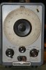
I agree. Would you believe that one of the best sine wave audio generators I use to this day is my old HP 201C (lovely image attached). There being the "wien bridge etc". Then I have a collection of old Wave Tek function generators, an old Data Pulse pretty good pulse generator plus an old HP 3311A small basic function generator. Quite the family. :)

Ron
 

Attachments

  • 201C HP.jpg
    201C HP.jpg
    263.8 KB · Views: 134
Thanks for all inputs.

I supposed that Function generators are low diistortion SO THAT do not affect the parametris of the circuits being tested. Now I see that I was wrong! Before reading the posts of this thread I thought maybe My function generator is nit a good one or maybe uses the OP-AMP's to generate square/ramp/ Sine waves.

What is the difference between a function generator and an audio generator other than the frequency response? Is an audio generator capable of generating non sine waves too?
 
Last edited:
Your function generator is just fine for what it is intended to be.

What is the difference between a function generator and an audio generator other than the frequency response? Is an audio generator capable of generating non sine waves too?

A function generator generates several types of waveforms. Typically, sine, square and triangular and working from there. They can get pretty elaborate as to the wave shapes they generate. When it comes to the sine wave in particular then it is a matter of how the wave form is actually generated. I mentioned for example DDS (Direct Digital Synthesizers). This paper is a pretty good read on the subject. I suggest you read it. There is also the true wein bridge oscillator circuit used to produce very high quality sine waves with excellent spectral purity. A Google of wein bridge oscillator should bring up a new wealth of information.

You select test, measurement and diagnostic equipment based on the intended application. If I need a truck I don't select and buy a sub compact automobile. :)

Hope that helps
Ron
 
Harmonic content:

How low is low?

How low do you need to go?

******WARNING WARNING decibels ahead*******
Those of a nervous disposition should close this thread now.:D

Looking at the screen dump of the spectrum analyser, there is a tabular display of the amplitude of the fundamental and the harmonics.
I just did a quick calculation and the 2nd harmonic is 37db down on the funadamental, and the third harmonic is 33db down on the fundamental.
Looking at the spectrum display, the vertical divisions appear to 10db, although I cannot see that specifically stated on the screen dump, and the harmonic levels agree with my quick calculations.
Unless you are looking for real harmonic purity that is not too bad.
1% would be 20db down on the fundamental, and 0.1% would be 30db down.

Running the oscillator or function generator with the output unloaded probably would not cause any problems like increasing the harmonic content of the signal.
However, overloading the input to the spectrum analyser will certainly make the harmonic content look far worse.

Happily there is a very easy way to tell if the analyser input is being overloaded, reduce the input to the analyser by 10db, the fundamental and all the harmonics should reduce by 10db.
If the analyser is overloaded, the fundamental will reduce by 10db and the harmonics will reduce by a lot more than 10db.

JimB
 
1% would be 20db down on the fundamental, and 0.1% would be 30db down.

Are you sure of that?!

Furthermore I would like to know how do you treat with the dB values you mentioned above?
Do you try to convert them to there decimal values so that understand them??

P.S How to treat the measurement instruments while they produce harmonics and can cause wrong responses?
 
Are you sure of that?!

Considering power,

db = 10Log(P1/P2)
db = 10Log(1/100) = 10Log(0.01) = 10x(-2)
db = -20

So, the answer is: yes, I think so.

Furthermore I would like to know how do you treat with the dB values you mentioned above?
Do you try to convert them to there decimal values so that understand them??
Having worked with dbs for many years I have a feel for them.
I generally dont need to convert them to anything.

P.S How to treat the measurement instruments while they produce harmonics and can cause wrong responses?
You have to understand the limitations of your test equipment.

JimB
 
Jim,

You know that an Spectrum analyzer is scaled for VOLTAGE vs frequency. I do not know why you went to measure the dB for POWER?!
I always Can not realize if the dB values are based on dB volt or dB power. For instance In your post (#25) I calculated the dB values based on VOLTAGE not power.
 
The harmonics of distortion are always measured in voltage because the impedance of a speaker varies all over the place when the frequency changes so the power also varies all over the place. The output voltage of an amplifier is steady when the frequency changes within its bandpass.
 
That's curious audioguru and dr.power, because human hearing is logarithmic. Yes complex impedance varries, but it's constant harmonic distortion at any frequency can be measured. It sure isn't easy though. Hearing is logarithmic on output power, not voltage, because output power is computed from a calibrated receiving microphone.

In the real world there are no voltages or currents associated with hearing, only one thing exists, pressures waves agitating the cilia of our inner ear, sometimes through bone conduction most often through the aural cavities, at least perceptually.
 
The output voltage of an amplifier is logarithmic like our hearing. The frequency response, distortion and noise level are measured in voltage dBs, not power dBs.
 
Which is weird AG. Because our ears measure received power.
 
-3dB is 0.707 times the signal voltage which produces 0.707 times the signal current. 0.707 times 0.707= half the power.
+3dB is 1.414 times the signal voltage which produces 1.414 times the signal current. 1.414 times 1.414= double the power.

Since our hearing and vision are logarithmic then 3dB is a small change of loudness or brightness.
 
You're having a discrepancy between perceptual effects vs measurable ones. What does it matter what your instruments can pick up if in a practical application they're not perceivable to the target? Modern measuring devices are so good we can pick up signals WELL outside of the devices ability to receive them.
 
Jim,
You know that an Spectrum analyzer is scaled for VOLTAGE vs frequency.

Is it really, well, well, well.

I can only suggest that you have a good look at the screen dump which you posted, think an bit and possibly RTFM.

At the bottom left hand side, the display shows the voltage levels of the spectrum components.
Fundamental 4.05 Volts
2nd harmonic 53mV
3rd harmonic 85mV

This is why I used the voltage expression for the level of the harmonics w.r.t. the fundamental.
The 2nd harmonic is 0.013 (as a simple ratio) of the fundamental.
But on the spectrum display it is just over half the height of the fundamental, does this not strike you as just a bit odd?
53mV is not just over half of 4.05 Volts, is it?

There are seven vertical divisions on the display, each division is 10db.
I calculated that the 2nd harmonic was 37db down on the fundamental, look at the screen, the 2nd harmonic is 3.7 divisions below the fundamental.

Is it sinking in yet?


I do not know why you went to measure the dB for POWER?!
It seems reasonable to me to measure the distortion as a fraction of the power.

I always Can not realize if the dB values are based on dB volt or dB power. For instance In your post (#25) I calculated the dB values based on VOLTAGE not power.
DeeBees are DeeBees!
There is no difference between voltage and power.
This has been explained quite recently in discussion here on ETO.

Try some simple calculations:

If there is 1 volt across a 1ohm resistor what is the power dissipated in the resistor (answer 1watt).

If there is 10volts across a 1ohm resistorwhat is the power dissipated in the resistor (answer 100watts).

Now calculate the dbs for 1 volt and 10 volts
and
calculate the dbs for 1 watt and 100 watts.
(answer 20db in BOTH cases)


JimB

That's right. Anyway I do not know if the load (the scope and the function generator wires) are supposed to be considered as pure resistive loads? If there happens to be a reactance (impedance actually) part then the load would not be CONSTANT at all frequencies. Please remember that we are talking about Harmonics which are a function of the frequency and hence the impedance would not be constant at each harmonic than the other...
 
At the bottom left hand side, the display shows the voltage levels of the spectrum components.
Fundamental 4.05 Volts
2nd harmonic 53mV
3rd harmonic 85mV

This is why I used the voltage expression for the level of the harmonics w.r.t. the fundamental.
The 2nd harmonic is 0.013 (as a simple ratio) of the fundamental.
But on the spectrum display it is just over half the height of the fundamental, does this not strike you as just a bit odd?
53mV is not just over half of 4.05 Volts, is it?

There are seven vertical divisions on the display, each division is 10db.
I calculated that the 2nd harmonic was 37db down on the fundamental, look at the screen, the 2nd harmonic is 3.7 divisions below the fundamental.

Is it sinking in yet?

Yea You are right,
SO what it does mean?
Is that mean that my spectrum analyzer has got a problem?
 
I think the biggest problem with your spectrum analyser is the user.

The oscillator/function generator has some harmonics in its sinewave output, so what?
They are not excessive for most purposes.

The spectrum analyser is just telling it as it is.

You on the other hand seem to refuse to understand all that is explained to you.

JimB
 
I mean what is the problem by this:

This is why I used the voltage expression for the level of the harmonics w.r.t. the fundamental.
The 2nd harmonic is 0.013 (as a simple ratio) of the fundamental.
But on the spectrum display it is just over half the height of the fundamental, does this not strike you as just a bit odd?
53mV is not just over half of 4.05 Volts, is it?
 
Status
Not open for further replies.

New Articles From Microcontroller Tips

Back
Top