Continue to Site

Welcome to our site!

Electro Tech is an online community (with over 170,000 members) who enjoy talking about and building electronic circuits, projects and gadgets. To participate you need to register. Registration is free. Click here to register now.

  • Welcome to our site! Electro Tech is an online community (with over 170,000 members) who enjoy talking about and building electronic circuits, projects and gadgets. To participate you need to register. Registration is free. Click here to register now.

Harmonics

Status
Not open for further replies.
Was the signal generator properly loaded/terminated? There are many things which can cause harmonics, the real world is VERY non-linear you've not mentioned at what signal strength these harmonics occur, that is VERY important.
 
... so obviously you don't have a pure sine wave there. The question is, where are those harmonics coming from: the scope? spectrum analyzer? the signal generator itself? something else?
 
carbonzit, that's not true, the signal generator could be generating a pure sine wave, the non linearity doesn't have to come from the source, it could be ANYWHERE on the path and more than likely an interaction between the generator and the analyzer itself, that's why I asked about loading, you can't just plug in a frequency generator and a scope and get good results, the signal generator has to be loaded, and the scope has to be a very minor portion of that load.
 
Was the signal generator properly loaded/terminated? There are many things which can cause harmonics, the real world is VERY non-linear you've not mentioned at what signal strength these harmonics occur, that is VERY important.

The signal generator is directly connected to the scope without any load. Do I need to add any load?

Please look at the below pic for your last question.
Actually the waveform seems to not be a pure sine wave, But I am not sure what is the problem? Maybe the signal generator itself originally does not able to produce a pure sine wave. Maybe the scope is not calibrated so good or has any problem and.... I do not know really!
 

Attachments

  • 1.PNG
    1.PNG
    66.4 KB · Views: 195
  • 2.PNG
    2.PNG
    72.4 KB · Views: 198
carbonzit, that's not true, the signal generator could be generating a pure sine wave, the non linearity doesn't have to come from the source, it could be ANYWHERE on the path and more than likely an interaction between the generator and the analyzer itself, that's why I asked about loading, you can't just plug in a frequency generator and a scope and get good results, the signal generator has to be loaded, and the scope has to be a very minor portion of that load.

Sorry but does not make any sense.
I think maybe it is clear that the scope-function generator must work just fine together without any load, otherwise they would not be able to properly monitor a measured circuit...!
 
The generator has a distortion spec of 1% at some unknown output voltage. How far down are you harmonics?
 
dr.power, please provide specs for your function generator. You can not feed an unloaded function generator into an unloaded scope and not expect bad things to happen, a load of some type is required, doesn't necessarily need to be large, could be 10/100k resistor, but you can't not present a load, it destroys the feedback circuits ability to regulate, it'll oscillate any which way it feels like because there's nothing to dampen the feedback.
 
Last edited:
dr.power, please provide specs for your function generator. You can not feed an unloaded function generator into an unloaded scope and not expect bad things to happen, a load of some type is required, doesn't necessarily need to be large, could be 10/100k resistor, but you can't not present a load, it destroys the feedback circuits ability to regulate, it'll oscillate any which way it feels like because there's nothing to dampen the feedback.


I just connected a 4.7K resistor both in parallel & in series with the function and scope.
There was no difference regarding the harmonics....
 
The first question is how the function generator actually generates a sine wave? I did look at the data sheet and saw no mention. Many function generators use what is called Direct Digital Synthesis (DDS) to generate wave shapes. Simply put the sine is really a synthesized sine wave.

It is not at all unusual to see the harmonics you are seeing. Generally the question is how far down from the fundamental are the harmonics? This is generally specified in db and part of the specifications sheet for the function generator.

For example last week I bought one of these units. By standards it is not a high end unit at about $1,800 USD. Look at the data sheet in the link and note Wave form Characteristics and where they spell out Harmonic Distortion of Sine Wave. I bought this because right now we have a dozen projects running and I have engineers trying to kill each other over want of a simple good function generator. Peace in the valley prevails.

So is Harmonic Distortion normal? Absolutely! The question becomes how far down from the fundamental each harmonic level is.

Just My Take
Ron
 
On a side note: Impedance 50<±10% means your function generator is designed to work into 50 Ohms. That being at the load point. Meaning if you are running into a scope that does not offer a 50 Ohm input impedance you would place 50 Ohms across the signal at he load (scope) input.

Ron
 
It is a Function Generator, not a Low Distortion Audio Signal Generator. So of course its distortion is pretty high.
 
Hi Guys,

I have got a MATRIX "MFG8216A" function generator:
https://www.yeint.fi/index.php?main...d+testing&subProductGroup=Function+generators

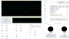
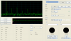
Today I connected it to my scope to see the waveform and FFT,
The signal was a 40kHz sine wave, the FFT showed harmonics at 80KHz, 120KHz...
Is that natural? The pure sine waves do not have any harmonic. so..?

Hi there,

As others have pointed out already, the 'function generator' may not put out a very perfect sine wave and/or the load may not be correct for that kind of generator.

One simple test you can do is to build up a little bandpass filter to pass the fundamental (like 20kHz) and see how much that bites into the other harmonics. You can then do either a simulation or a calculation to determine if it brought down the harmonics (and possibly some of the fundamental) as the filter should have done, and that will tell you if the harmonics are coming from the generator or not. If that's the case (and most likely it is) you can use a filter like that to get a much more pure sine wave if that is what you are after.

There are various kinds of passive filters if you would like to see one just let us know or do a search.
 
Originally Posted by ronsimpson **broken link removed** The generator has a distortion spec of 1% at some unknown output voltage. How far down are you harmonics?
Sorry I can not understand what you are trying to say.
The question is: what is the amplitude of the harmonic frequencies as compared to the fundamental frequency (how many dB down from the fundamental)? That will allow you to approximate the percent distortion.

Edit: If it hasn't already been noted, 1% distortion is not generally visible on an oscilloscope trace of a sinewave.
 
Last edited:
Edit: If it hasn't already been noted, 1% distortion is not generally visible on an oscilloscope trace of a sinewave.

1% is about the limit of visibility, but you'd be hard pushed to tell - however, it will show clearly on his FFT trace, which is what he's looking at.

Basically he's worrying about nothing.
 
I may be off on this but generally when distortion was specified as a percent (such as < 1% value) it applied to total distortion for a sine wave. The total distorting being Harmonics + Hum + Noise. With the hum and noise riding on the peaks and valleys. Anyway I don't see anything out of the ordinary.

Ron
 
I may be off on this but generally when distortion was specified as a percent (such as < 1% value) it applied to total distortion for a sine wave. The total distorting being Harmonics + Hum + Noise. With the hum and noise riding on the peaks and valleys.

Yes, but it doesn't really apply in this case as the function generator output will be at such a high level as to swamp any noise or hum, plus it's a very low impedance source, which will prevent pickup.

Anyway I don't see anything out of the ordinary.

Not for a function generator.

Basically function generators aren't intended to be low distortion, or used for audio testing - it's a crude general purpose waveform generator.

Usually they generate square and triangle waveforms, with the triangle then been crudely shaped to approximate a sinewave.

For an audio generator, you would generate a sinewave (wien bridge etc.) for a very low distortion (0.01% wouldn't be uncommon), and then overdrive and clip that to generate a squarewave.
 
Status
Not open for further replies.

Latest threads

New Articles From Microcontroller Tips

Back
Top