Continue to Site

Welcome to our site!

Electro Tech is an online community (with over 170,000 members) who enjoy talking about and building electronic circuits, projects and gadgets. To participate you need to register. Registration is free. Click here to register now.

  • Welcome to our site! Electro Tech is an online community (with over 170,000 members) who enjoy talking about and building electronic circuits, projects and gadgets. To participate you need to register. Registration is free. Click here to register now.

supressing harmonics in transformer

Status
Not open for further replies.

lokeycmos

New Member
i built this circuit just for fun:


https://electroschematics.com/220/12v-dc-220v-ac-converter/


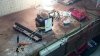
It is a square wave oscillator. i subtituted high power mosfets for the darlingtons. the circuit works great, but there is a lot of harmonic buzzing comming from the transformer. it draws 2 amps at idle. my question is, is there a way to suppress of get rid of the unwanted buzzing harmonics? mabey a capacitor somewhere? the transformer does not buzz when fed properly with mains. i am reading 60hz on the output.
 

Attachments

  • inverter.jpg
    inverter.jpg
    907.4 KB · Views: 169
When designing a transformer, an engineer assumes a sinewave. A square wave has 11% more volt-seconds than a sinewave with the same peak voltage.
In addition, the circuit indicates a 2X10 v secondary......With a mosfet, you are perhaps dropping only about 0.2v, so you are applying 11.8v to a 10v winding.
And with a square wave to boot.

You are saturating the transformer.

EDIT: 2 amps at idle times 12 volts, that's 24 watts, that is a lot of losses.......
 
Last edited:
The 10V RMS rating of the transformer has a peak of 14.14V so the 12V peak of the squarewave DOES NOT cause saturation.
A cheap transformer does not have enough varnish to hold the laminations of the core tightly together so of course it buzzes when fed a squarewave.

The high idle current is probably caused by "shoot-through" current because the extremely simple circuit does not have any dead-time between pulses. Then one side is not completely turned off yet when the other side turns on.
Also, the fairly low current from the Cmos IC slowly charges and discharges the high gate capacitance of the output mosfets so they ramp instead of quickly switch.
 
Audioguru
we could have a 100+ post arguing and counter-arguing this, but the important fact is that the circuit is losing 24 watts at idle, that is very large amount.
 
The core is probably saturating. Running at 120hz should help that. Many appliances really don't care what frequency you are running.
It looks to me that the transistors are running at 50%. The transistors are both on at the same time (for a couple of micro seconds).
I don't like Darlington transistors in this application. They have a large voltage drop. Easy they eat up 10% of your power.
 
Do you have some insulation between the transistors and the heatsink, like mica or silicon foil?
 
One of the easier tricks to solving the harmonics issues is to use a drive circuit that allows for PWM adjustment of the two halves.

By making a larger dead band between each half you can narrow the pulses to a point where its possible to add capacitance on the secondary circuit to help smooth off the square wave switching edges into a somewhat smoother sine wave.

Granted its not perfect but it does help considerably on cutting down switching noise and the energy wasted by it while at the same time giving a cleaner output wave form.
 
The 10V RMS rating of the transformer has a peak of 14.14V so the 12V peak of the squarewave DOES NOT cause saturation.
..............................
Not necessarily true. If you calculate the peak magnetizing current for a sinewave and a squarewave for the above voltages and same frequency you will find that the square-wave peak current is about 33% higher than the sinewave peak current. That could easily saturate a cheap transformer.

Even with the same RMS sinewave and squarewave voltage and frequency the squarewave will still generate about a 12% higher magnetizing current.
 
Last edited:
Status
Not open for further replies.

New Articles From Microcontroller Tips

Back
Top