First of all, here is how I am testing my circuit:
I'm using a software oscilloscope with coaxial cables running as scopes.
I'm using a repeating strum of low E string as my testing input recorded and played through the same computer.
Secondly, odd stuff:
When I connect the scope directly to the recording, the oscilloscope shows a close-to-square wave presentation of the sound.
I can not get the proper square wave anymore, every time string is plucked i get twice the frequency (at the beginning of each strum, this could be normal and be eliminated through software)
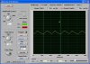
When there is nothing connected to the input,
here is the output I get. (shifting/moving)
When the cable from the pc is connected to the input but nothing is played through the soundcard,
here is the output I get.(shifting/moving)
Is the 1.1Vpk signal you posted earlier superimposed on the 2.54Vdc.?
What do you mean by superimposed?
You should have the Vinput connected, with the Vin set to zero, when you take these measurements...
Remember its a high input impedance opa.
You mean Vin set to 0 on oscilloscope settings?
I think the circuit is on a breadboard with long wires all over the place acting like antennas to pickup mains hum.
And/or the input cable is not shielded audio cable.
Yes, the circuit is on a brand new noiseless breadboard.
Yes, there are a lot of wires running over the breadboard, the longest is about 13cm.
Input cable is coaxial.
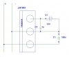
When the input is shorted then the output is normally low (or if the input offset voltage was different then it would be normally high at about 7.8V). The output should switch from 1.4V to 7.8V when there is a signal. it needs to be attenuated so its max voltage is 5V.
I do not understand very clearly what you mean here. Can you expand on it?


 Wouldn't just lower resistance dividers and a higher value bypass capacitor do fine? Is there a final value that I should achieve here or a ratio between the dividers and the bypass?
")