The datasheet for the LM324 explains that the output will suddenly go high or low when its input voltage goes negative more than 0.3V.
This is meaning the input Vmax≤+0.3V Vmin≥-0.3V, right?
Assuming my guitar outputs 3mV; which you thought was too little, the first stage shouldn't have a phase reversal.
If I misread my voltmeter and the guitar output was 30mV, the first stage still won't have a large enough input to have phase reversal; yet 30mV×11= 0.33V will cause a phase reversal on the 2nd stage.
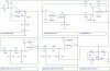
The output from a guitar's pickup could be driving the input of the first opamp well below ground. If you add the FET preamp (that I posted) to the input then the input of the opamp will not go below ground and there will be no phase reversal.
What if I changed R5 value to 3MΩ, would that help?
Can't I redesign the opamp based preamp for a higher input impedance like that?
If I was to build the FET preamp you suggested, will that be replacing the current first stage(the preamp)?
I think something is wrong with your 'scope. A power amp is not needed since the input of a PIC is a high resistance load that is easily driven by an opamp. Maybe the input of your 'scope is a low input resistance mic input instead of a high input resistance line-level input.
Is the reason behind using Hi-Z inputs for audio applications prevent clipping?
I had mentioned this before; I was using my laptop's mic input for scope.Maybe I should switch to my desktop and use the line input?
")
I'm guessing that this could be my problem..
**broken link removed** My next laptop is going to be an apple...