ThomsCircuit
Well-Known Member
Im glad I decided to make this project. It looks simple enough but it does require design considerations that I dont fully understand. Currently China is on lock down so acquiring some parts is extremely slow. A project I submitted for fabrication to JLCPCB has been stalled in the delivery que for over a week so Ill focus on these issues here.
Vias.
I havent noticed them until i started this project. Now i see them on ready to purchase modules like this one. It was suggested that i add some around the ground track by pin 1 of MP2315. My PCB program does not have this feature so i would need to do this manually. Problem is i dont know how many, how big, or how close they should be. Trying to understand the many different vias but it can get confusing. It was suggested that a pour around a net would be better than adding an array of vias.

---------------------------------------------------------------------------------
Ground Loops
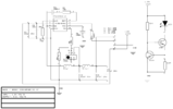
I know nothing about this. Well I cant say that. I do know the tracks should be as close as possible. This PCB is 30mm x 30mm. How do i tell if ive connected these in the right order? Do you need to see the schematic to understand if the PCB is optimally designed. If so I attached it.

----------------------------------------------------------------------------------
Net Pours.
sometimes when you show someone a new tool they tend to use it for everything. Have i done that here? Do I have too many separate pours on this pcb? I mean tracks should be wide enough to provide the voltage required so why not surround that track (net) with a polygon and pour a big fat copper pour around it. Boom problem solved. Well I did that and then did another, and another, and another. So if you can make sense of my image ive got quite a few net pours for signal and current nets and then a ground pour. I colored a few nets for clarity.
The blue colored tracks represent the ground track. Its pour makes a continuous connection of every pad and through-hole. With wide and sufficient spokes. And then one huge GND plane on the bottom too.
The 12V is in a tan color (has no pour) Ive highlighted one net pour in grey.
If you look closely you can see the outlines of the other net pours. Im concerned I may not need every net to have a pour. I mean these pours place nets very close to one another right? Is that good for this buck module?

Vias.
I havent noticed them until i started this project. Now i see them on ready to purchase modules like this one. It was suggested that i add some around the ground track by pin 1 of MP2315. My PCB program does not have this feature so i would need to do this manually. Problem is i dont know how many, how big, or how close they should be. Trying to understand the many different vias but it can get confusing. It was suggested that a pour around a net would be better than adding an array of vias.
---------------------------------------------------------------------------------
Ground Loops
I know nothing about this. Well I cant say that. I do know the tracks should be as close as possible. This PCB is 30mm x 30mm. How do i tell if ive connected these in the right order? Do you need to see the schematic to understand if the PCB is optimally designed. If so I attached it.
----------------------------------------------------------------------------------
Net Pours.
sometimes when you show someone a new tool they tend to use it for everything. Have i done that here? Do I have too many separate pours on this pcb? I mean tracks should be wide enough to provide the voltage required so why not surround that track (net) with a polygon and pour a big fat copper pour around it. Boom problem solved. Well I did that and then did another, and another, and another. So if you can make sense of my image ive got quite a few net pours for signal and current nets and then a ground pour. I colored a few nets for clarity.
The blue colored tracks represent the ground track. Its pour makes a continuous connection of every pad and through-hole. With wide and sufficient spokes. And then one huge GND plane on the bottom too.
The 12V is in a tan color (has no pour) Ive highlighted one net pour in grey.
If you look closely you can see the outlines of the other net pours. Im concerned I may not need every net to have a pour. I mean these pours place nets very close to one another right? Is that good for this buck module?


