Continue to Site

Welcome to our site!

Electro Tech is an online community (with over 170,000 members) who enjoy talking about and building electronic circuits, projects and gadgets. To participate you need to register. Registration is free. Click here to register now.

  • Welcome to our site! Electro Tech is an online community (with over 170,000 members) who enjoy talking about and building electronic circuits, projects and gadgets. To participate you need to register. Registration is free. Click here to register now.

Float Charger + Emergency switch

Status
Not open for further replies.

Wastedfun

New Member
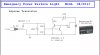
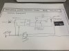
Okay, I am working on an emergency LED lighting that will run off a 6v battery when the lights go out. I attached what I have now. I have the battery ordered and on the way but I am not finding the right charger. I found that I will need a "Float Charger" to make sure the battery is not over charged as it will stay connected all the time. And MrAl was kind enough to provide schematics on how to create and electric cut off switch.

Issue is, the cut off switch is being ran from a DC source. So I THINK i have to connect the +/- from the Float charger to the line in on the schematic. So when power is on the float charger is providing power to the battery and the LED's are not on. But from what I have gathered by testing my camera charger is that the float charger will start to pulse on and off when its full, basically testing the charge and turning off over and over. This means the emergency switch will activate and deactivate over and over and turning the LEDs on and off.

I haven't tested this because I don't have a charger yet (Well, I do but I have a 12v float charger and getting a 6v battery. So i screwed my self when i ordered the wrong voltage...uhg(its a 12v 500mA)) but when I get one I think this is what will happen. I cant hook the schematics power source behind the float charger circuit because then it will over charge the battery.

All I want to do is have an AC line go to a transformer (float charger) to keep the battery charged but use the same power source to control the switch and activate the LED's. :confused::confused::confused::confused:

Any ideas?
 

Attachments

  • em1.jpg
    em1.jpg
    98.4 KB · Views: 187
Hi,

Are you saying you ordered a 6v float charger or you want to build your own using the same transformer as in that schematic?

If you order a 6v float charger and it is isolated from the line you can connect that to the battery and that should work ok. But you'll have to make sure it is isolated. It probably is though.

If you want to build your own then we can find or design something. The simplest designs use the LM317 linear regulator. The main points of the charger are full charge voltage set point and current limit, and float voltage set point. If you design your own you can go back to a full wave bridge rectifier unless you still have other stuff common to one transformer lead.
 
I ordered a 12v float charger so I need to order a new 6v one to match battery. But my question was on the design you made MrAl, if I use the float charger as my DC source to activate the LED's and to charge the battery, will it pulse on and off? because the float chargers pulse when the battery is full. I cant hook up a constant line to the schematic above because i think that it will give constant current to the battery and over charger it. Only Idea I had for that was to throw is a diode to make it only push one way out from batter and just hook up the charger on separate circuit.
 
Hello,

If it is a float charger that it is made for that purpose so it may not work as a power supply. It's hard to tell though without knowing the circuit of the charger.
 
Okay, so i was thinking then i can add a diode that will force voltage 1 way away from battery and then hook up tge charger seperate
 
Hi,

Yeah it's tricky because if the float charger has to connect directly to the battery (and it does to sense voltage correctly in most cases) then you cant also use if for sensing. A diode probably wont help either because we cant use a diode between the battery and float charger.
However, a very small wall wart would work well enough to use as the transformer in that circuit. Any voltage around 5v or more would work.
 
I mean if i can tap into the battery charger DC out befor it hits the float charger i can connect the constant voltage to the schematic above to power the on off circuit. Then on the right side of the circuit that connects to the battery, force a one way flow from the battery to the LEDs and then hook the float charger to the battery directly so it can charge. Think will work that way?
 
Hi,


Oh i didnt realize you had access to the low voltage DC side of the float charger. There may be a way to do this and that might work.
However, you can not make the connection between the input (-) side and ground of the circuit unless the float charger has a common ground.
So the question is, does the charger have a common ground?
 
Well the 12v charger that i have now, looks like that. Where the float circuit is seperate. But i cant use that because its too high voltage. I havent gotten a 6v one yet because i didnt want to order another item without working out the details first.

Problem is most 6v have the transformer and the float circuit all in one pc. So i may use a whole seperate dc source.

But what is "common ground"?
 
I ordered a charger that will provide 6v charge to the battery and have a separate dc line from the transformer that i can tap into. When it get here I will post it up.
 
Can you post a link to your 6V charger so that we can check its spec?
 
a charger that will provide 6v charge to the battery and have a separate dc line from the transformer that i can tap into
:confused: The adapter (transformer) in the link has an AC output (12V, 0.33A). That AC voltage (at the input to the charger module) will be the point to monitor mains failure.
 
ah what the heck. I didnt notice that. damn another thing i order and is messed up in some odd way. Can I still use that ac output for the switch circuit?
 
Hi,

You should be able to use that anyway. Probably with a capacitor and full wave rectifier. The cap will isolate the wall wart from the circuit for DC, but allow AC to activate the sense input. You'll need to use a non polarized cap maybe 0.1uf and then lower the value of the filter cap in the detector circuit to 0.1uf also. We'll have to see if this works ok.

Here's a method that should work regardless which lead the wall wart is common with on the output...

In place of the transformer in that previous schematic, use two capacitor 0.1uf each. They go from the AC wall wart output to a full wave bridge rectifier. The output of the rectifier goes in place of the transformer secondary.
So what we are doing here is detecting the AC by coupling the AC to the bridge, then use the bridge output as the DC detector source to drive the transistor. A 10uf cap should be ok for the filtering.
 

Attachments

  • em2.gif
    em2.gif
    12.6 KB · Views: 191
Last edited:
Hi,

Yes that's not a problem. The main problem was keeping the output leads from the wall wart from connecting directly to the ground (negative side of battery) because that could screw up the charging circuit. But we still had to make it common to the detector circuit (diodes, transistors) so that it could drive the base of that one transistor. Notice that the max voltage that could get through would be 0.7v because the base emitter keeps the incoming voltage at that low level. Even if something went wrong with the transistor circuit the two 0.1uf caps would hardly provide any charge current...a truly insignificant level.

Take a few measurements after you get it hooked up and make sure the battery charges properly and everything works as planned.
 
Hi,

You're welcome, and i hope you can post some pics of the project at some point so we can all take a look firsthand :)
 
Status
Not open for further replies.

Latest threads

New Articles From Microcontroller Tips

Back
Top