Continue to Site

Welcome to our site!

Electro Tech is an online community (with over 170,000 members) who enjoy talking about and building electronic circuits, projects and gadgets. To participate you need to register. Registration is free. Click here to register now.

  • Welcome to our site! Electro Tech is an online community (with over 170,000 members) who enjoy talking about and building electronic circuits, projects and gadgets. To participate you need to register. Registration is free. Click here to register now.

Float Charger + Emergency switch

Status
Not open for further replies.
Hi,

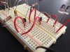
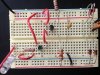
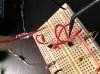
Dont worry about feeling a little funny about it that was a nice diagram. I like the way you added actual pictures of the stuff to the drawing as that brings it to life a little more.

But one thing you dont have to do is do tests that i dont request. When you connect the LED across the AC for example you may have damaged the LED. it may not be apparent right away either. But you did connect it across the 10uf cap and you got it to light, so that's good. That means we at least have some signal getting to the lower transistor base.

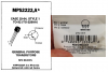
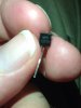
What are the actual part numbers of the transistors?
BTW how bright is the LED that was originally always lit up (the one connected to the battery)?


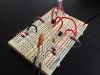
Next, short out the lower transistor collector to emitter and see what happens to the LED that is already in the circuit (no need to connect another LED yet).

Just so you know, we are now in the troubleshooting mode to find out what exactly is stopping the circuit from working as it should.

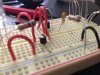
Also, the two smaller capacitors help to isolate the wall wart from the detector circuit so that connecting it to the battery doesnt hurt anything. There's no short for DC.
 
I matched the part numbers to the one in the schematic. The 2222 ones. I took out the resistor to the white leds and ran two in sequence, they are bright. But i have 100 of them so if they burn out during testing, no worries, same for the tests i did. Im using red leds from the shack and have a few incase one burns.

When i get off work i will do the others tests

Thank you
 
Ok i connected the first trans collector and emitter and the leds turned off while the ac plug was not even plugged in
 

Attachments

  • image.jpg
    image.jpg
    1.3 MB · Views: 137
Crap. I checked the trans models and i found the error, they are not right ones!
 

Attachments

  • image.jpg
    image.jpg
    410.3 KB · Views: 155
  • image.jpg
    image.jpg
    1.1 MB · Views: 156
The datasheet for an MPS2222A transistor shows that it has exactly the same spec's and pins as a 2N2222A transistor.
 
Ah so thats not the problem :( was hoping for easy fix lol.

I tried both way on trans to see if I had em and co mixed but didnt fix it. I figured was right because I used the graph from the package but was worth a shot.
 
Hi,


Yeah there is a wiring error. From the PICs it seems the transistors are not wired properly. Check the drawing for the transistors and be sure to get the C and E terminals correct. It has to be wire perfectly before it will work.

After you rewire, take another pic or two one from the top and post.
 
I tried both way on trans to see if I had Em and Co mixed but didnt fix it.
That is the best way to destroy a transistor.

I figured was right because I used the graph from the package but was worth a shot.
RadioShack knows NOTHING about electronic parts and frequently show the wrong pins. Simply look on the datasheet from the manufacturer. The MPS2222A was made by Motorola/Freescale and can be seen at www.datasheetarchive.com or on Google Images.
 
Okay, I fixed the transistors, and even replaced them with new ones, just incase the old were messed up. Still...LED's not turning off when I plug in AC. :(
 

Attachments

  • wire (1).JPG
    wire (1).JPG
    2 MB · Views: 134
  • wire (2).JPG
    wire (2).JPG
    1.9 MB · Views: 142
  • wire (3).JPG
    wire (3).JPG
    2.2 MB · Views: 141
  • wire (4).JPG
    wire (4).JPG
    2.3 MB · Views: 127
It is too bad that RadioShack shows the bottom view of the transistor's pins instead of the normal view.
 
The breadboard wiring is so messy that I cannot see what connects to what.
The circuit is very simple, here is how it works:
 

Attachments

  • emergency switch.png
    emergency switch.png
    10.4 KB · Views: 146
As far as I can see from the pics in post #50 there are several wiring errors:-
Both transistors have their collectors connected to the +ve rail.
The battery -ve terminal is connected to the +ve rail.
Neither transistor has its emitter connected to the -ve rail.
A 10 k resistor has been used instead of the 100k.
From the sound of this, my understanding of schematics is completely wrong.
 
Hello,

Well then we'll have to work with the photos of the breadboard itself.

From that most recent pic, there are still several wiring errors. See attachment. Move the three wires into the other holes as shown near the top left, remove the resistor with the big red "X", and rotate the transistor near the bottom of the drawing with the blue-green circle on top 180 degrees so it is oriented the same as the transistor near the top.

Take another pic from the top like that one and we'll see if everything is right. It may turn out that that bottom transistor is also burnt out, but dont use any more transistors until the wiring is verified, unless of course you have a lot of transistors on hand.
 

Attachments

  • wire5b.JPG
    wire5b.JPG
    207.8 KB · Views: 144
From #57: "rotate the transistor near the bottom of the drawing with the blue-green circle on top 180 degrees so it is oriented the same as the transistor near the top"

Swap E and C.

Post another pic.
 
Status
Not open for further replies.

Latest threads

New Articles From Microcontroller Tips

Back
Top