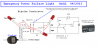
So I have made this AC schematic and it will not work. The LEDs stay on all the time from the battery and the line from the wall wart does not turn it off. I tried taking it all apart and starting over from scratch, just to make sure I didnt mess it up, still nothing. I got the first schematic to work but it was with a DC current and I still need to keep the AC current away from the battery.
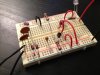
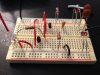
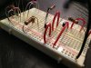
Any ideas what I missed? I dont know if it will help but I will attach what I have.
Any ideas what I missed? I dont know if it will help but I will attach what I have.
Attachments
Last edited:
")