Continue to Site

Welcome to our site!

Electro Tech is an online community (with over 170,000 members) who enjoy talking about and building electronic circuits, projects and gadgets. To participate you need to register. Registration is free. Click here to register now.

  • Welcome to our site! Electro Tech is an online community (with over 170,000 members) who enjoy talking about and building electronic circuits, projects and gadgets. To participate you need to register. Registration is free. Click here to register now.

Fade each color of RGB LED's with 555 / 4029

Status
Not open for further replies.
Anyway enough off-topic, I'm getting sidetracked (we have stuff waiting for them to get PICs back in stock).
As I pointed out above, they have pics available, maybe not the ones you require but one that is very fitting to this project. Sorry for off topic posts.

Mike.
 
Thank you for all the response and feedback about coding with software. I do have an interest to use software to control components but its not something i want to do now. I am still very new at circuits in general and have a good deal invested in analog components. I want to continue to understand how to solve my issues using this technology before i begin using another method. Id like to focus on solving any issues i may have with the project i posted while keeping it in its analog format. I understand there are better ways to make this circuit work but I have 95% of the components at my disposal to build this one. Im simply needing the transistors and the 4029. I researched and found this schematic online. While i do understand more than i did a year ago there is more here for me to learn. Now if you could help me understand what i could add or alter to make this project better, run cooler, id be grateful. Ive outlined some questions in post #1
This circuit is featured in this Instructables.

I am rather rusty at this level so I burned some time looking at this. If one were not using RGB LEDs the reds could be used as 4 serial chains of 2 saving 4 resistors. Pwft. Past that is buying 3 buck boost converters to power the LEDs in even longer strings with fewer current limit resistors. Again pwft.

You show 220R on all 3 colors in the the first schematic. Looks fishy!

For what it's worth having the parts on hand does not make it worth building. Wanting the experience does. Sometime you should try the PIC Pommie suggested. It is a LOT more fun.

3v0
 

Attachments

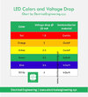
  • led-voltage-drop-chart-voltage-by-color.jpg
    led-voltage-drop-chart-voltage-by-color.jpg
    40.1 KB · Views: 232
You show 220R on all 3 colors in the the first schematic. Looks fishy!
That would be the original design. I would be using 100R for G&B and 130R for R.
8 leds with one color lit at a time will draw 160ma i would like to use transistor 3704 that has a 500ma dissipation. Enough to handle the load. Have i made a good decision?
 
Need to see the RGB LED data sheet to know.
OK I HAVE IT HERE.
RGB Common Cathode

Id also like to use 1/8 watt (125mw) resistors. ive calculated one color averages 30-50mw under 4.5 volts
Blue 3.0 fV 4.5v - 3.0 = 1.5 x 0.20 fC = 0.03 (30mw)
Green 3.0 fV 4.5v - 3.0 = 1.5 x 0.20 fC = 0.03 (30mw)
Red 2.0 fV 4.5v - 2.0 = 2.5 x 0.20 fC = 0.05 (50mw)
 
Hi

I think you'll have problems scaling up that circuit to drive more LEDs
The original fader is meant to drive a much lower current.
If you add a larger drive transistor, the transistor will require more base current to provide more collector current to the LED's. That would require lowering the value of the 10k base resistor, which would in turn, alter the fade times. This further complicates the circuit because of the limited amount of output current the CD4029 can provide (with 5v supply, it is vary small, about 500uA).

So...in my opinion, find a different circuit.
 
Even if you add more current output from 4029, the base resistor will have to be reduced.
Reducing the base resistor value will shorten the fade in/out time.
So I understand this, Just adding my voltage to the circuit will not improve the 4029's capability?
I mean im in no position to question to what your saying for i dont have the knowledge to challenge you so if there is nothing that can be done than ill continue to search for another circuit.
 
If you decrease the resistor value and increase the capacitor value both by the same factor the time will stay the same but the base current available will increase. From memory, the 74hc version can supply ~25mA. At school ATM so can't check.

Mike.
 
So I understand this, Just adding my voltage to the circuit will not improve the 4029's capability?
I mean im in no position to question to what your saying for i dont have the knowledge to challenge you so if there is nothing that can be done than ill continue to search for another circuit.
You are actually trying to rescale the circuit to accommodate a larger current load. I stated earlier that the circuit is not designed to "scale" well. By "scaling well" I mean that simply resizing the components and values will not work for this circuit. The emitter follower driver doesn't help either. The circuit needs to be redesigned.

I know that's probably not what you wanted to hear but...we were asked.
 
The circuit needs to be redesigned.
Ok you are correct. Where do we start? We can shape it using caps and resistors and the 555 will provide the timing. the 4029 is too weak so thats out. replace it with Pommie's suggestion or perhaps a darlington driver. We could use a 555 for each color.
 
If the original circuit worked then the combination of 1K and 1500uF will give 10 times the current. How much has the LED current increased?

This is why I suggested a micro earlier.

Mike.
 
If the original circuit worked then the combination of 1K and 1500uF will give 10 times the current. How much has the LED current increased?
Im sorry i dont know how to answer that. Each led has the following specs. One color is on at a time. Eight LEDS. 20millamps x 8 would be 160ma.
RGB LED Specs
Blue 3.0 fV 20ma
Green 3.0 fV 20ma
Red 2.0 fV 20ma

The transistor in the original design was 3904. It has a collector current of 200ma. I thought i should increase it so i subbed it with 3704 because it had a CC of 500ma. But thats just what i thought, i may not quite understand enough to know that.
There is also some concern that the 4029 cannot handle the load of the 8 LEDS. Still if it can be done with one LED I cant see why it cannot be done with 8 LEDS. Some components may need replacing but the basic logic is here it just needs adjustments to handle the increased current.
 
Status
Not open for further replies.

Latest threads

New Articles From Microcontroller Tips

Back
Top