Continue to Site

Welcome to our site!

Electro Tech is an online community (with over 170,000 members) who enjoy talking about and building electronic circuits, projects and gadgets. To participate you need to register. Registration is free. Click here to register now.

  • Welcome to our site! Electro Tech is an online community (with over 170,000 members) who enjoy talking about and building electronic circuits, projects and gadgets. To participate you need to register. Registration is free. Click here to register now.

Electret Microphone Interfacing

Status
Not open for further replies.

Omar.M

Member
Hey there,
I've been trying to interface an electret microphone with a PIC microcontroller for a gift I'd like to give to somebody.

I've tried a few circuits involving NPN transistors, LM358 and LM386 ICs. None of them have seemed to work for me (see below), as the output signals yielded no usable data for me (checked with scope and through a simple ADC-to-serial routine I churned out).

I think the issue is a damaged microphone, caused by incorrect placement into the breadboard (eventually causing the mic to overheat). I am not sure if that is the issue, or just due to the fact that I am testing this on a breadboard.

But since I'm going to be ordering some parts anyways, I'd like to grab the right IC for the job, along with what ever I need to get this thing working. Basically I'm trying to get as nice of a signal as possible to the microcontroller, enough to distinguish peaks in music with the mic placed no farther than 10 cm from source.

I was wondering if anyone had any recommendations. I've seen Audioguru's TL071-based circuits he has posted numerous times on the forums, but my circuit will be powered by 4-AA batteries so something in the 5V Vin range is what I'm after.

Thanks very much!


Links:
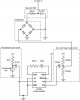
First schematic (Top section involving LM386N) **broken link removed**

I was fairly confident on this one until I tried it... very noisy output which doesn't work until I blow very hard into the microphone.

Second schematic I attempted: **broken link removed**
Still nothing.
 
You might try this circuit which works down to 3V. It will also operate on a single 5V supply if you substitute the LT1677 for the TL071 in Audioguru's circuit.
 
Hi Omar,
Your first circuit has a 10k pot feeding power to the mic. If its resistance was turned down then maybe the mic is burnt. An electret mic needs to have a 2.2k to 10k resistor to feed it power, not a pot. Your LM386 amp has a capacitor between pin 1 and pin 8 so its gain is 200 (but only at high frequencies because the capacitor value is too small). The LM386 power amplifier is also missing a supply bypass capacitor and the resistor in series with the capacitor at its output as shown on every circuit in its datasheet which prevents it from oscillarting at a high frequency.
You should NEVER make a circuit without looking at the important details of ICs in the datasheets.

I think breadboards casuse more problems than anything else. They are a mess of tangled wires and intermittent connections.
I use stripboard where all connections are planned and soldered and there is not a mess of tangled wires that are too long. Every circuit I make works perfectly.
The microcontroller senses the DC plus AC voltage at the output of the LM386 which averages +2.5VDC. It swings a max of +1V to +4V.

Your second circuit is better because the mic is powered from a 10k resistor from +5V but its extremely simple transistor amplifier might work or might not work depending on its hFE.

Please attach your schematics to your posts here where they stay instead of over at Flickr where they disappear soon.
 
Here's a Whistle Key Finder using a piezo:
**broken link removed**

And here's a microphone circuit:

**broken link removed**
 
Thanks very much for the replies.

Either of the posted circuits seem simple enough to build, it is just a matter of deciding which one would yield be a nice-enough output to be read by the microcontroller. The transistor-based circuit has a low part-count and would easily fit onto the PCB that I'll end up designing. Colin, do you find that it provides enough of a swing to detect loud and not-so-loud parts of a song (relatively). It seems you were using it for detecting a certain frequency in the sound, so it seems it may be sensitive enough based on the application of the posted schematic (if I understood correctly, that is).

Audioguru, I'll update the top post to attach the schematics-- thanks for your help as well. It wouldn't hurt to simply try a 10k resistor simply feeding the input and setting the correct bypass capacitor. I'm going to pick up some stripboard and make a semi-permanent circuit to tinker with.

The final question, before I purchase the parts including a couple of electret microphones, am I looking for one with the highest rated-voltage and lowest impedance? Digikey has a trillion options!
Thanks!
 
If you want to SAMPLE the audio, you should look at an op-amp circuit. My transistor circuits merely detect an audio signal.
 
Hi Omar,
I have never purchased an electret mic. I salvage them from old telephones, answering machines, intercoms and toys.
They all work from a filtered 3V to 12V with a series 3.3k (with a 3V supply) to 15k (with a 12V supply) resistor.
It should have a load resistance that is at least triple the value of the resistor that powers it. Therefore an opamp preamp should be non-inverting.

What will the micro-controller do with sounds? Peaks in music occur for each loud frequency. Maybe you want to make a peak detector circuit that will have a DC output for a certain duration for each loud peak. An amplified mic produces all frequencies in real time. The ADC input of the microcontroller can read the DC peaks but might get confused with AC at many frequencies.
 
Thanks Audioguru!

I think I should have been a bit more clear on the whole overview of this project. I've got a PIC micro, connected to a 5x7 LED matrix. Amongst other things, I'd like to have a setting where the display will "pulse" with external sounds. Sort of like an audio VU meter, but a bit... more graphical and less accurate-- purely novelty. So I guess I just need something that can give me enough range for me to generate about 7 steps of loud to low (no more resolution is needed).

I think it might be easiest for me to stay with the LM386 circuit, just make the necessary changes which you outlined above. Input resistor no lower than 2.2K (and no higher than 10k) and the necessary bypass cap / resistor as outlined in the datasheet. Do you think this circuit will have enough amplification?

Everything's pretty much done, just hoping to change a few min / max values, build the audio portion and put it together.

I guess it also feels wrong to just grab a schematic and build something without paying attention to the theory behind it. I was wondering if you had any literature I can read on this this subject (anything specific, otherwise I'll just Google for some op-amp tutorials / formulas needed to calculate the values components).
 
Your LM386 power amp circuit didn't work probably because the microcontroller didn't know that with no signal its output voltage is +2.5V and the loudest signal alternates from +1.25V to +3.75V. It has a gain of 200 which is plenty (maybe too much so a volume control trimpot might be needed).

If you want the LEDs to blink with the beat of music then you need a lowpass filter.
 
Ah. I think I understand now.

So a microphone signal needs to be amplified with a decent enough swing that a microcontroller can see a decent amount of the generated frequency. Audio itself is AC, and the microcontroller probably wants DC in the application I am using. So I need a peak detector and low-pass filter stage to take care of that.

So here's what I found from my searching. LM386 amplifier -> diode-based rectifier -> simple cap / resistor based low-pass filter.

Am I on the right track? Attached is a diagram that seems simplistic enough. Of course I don't require the line-level portion of the circuit, so if I just leave the supply bypass capacitor (220u) in and the 100k resistor connecting it to ground, it should be fine?

Thanks!
 

Attachments

  • diagram_0.jpg
    diagram_0.jpg
    111.6 KB · Views: 1,157
Last edited:
You want an amplifier that amplifies the 20mV signal from the microphone to produce about 5v. The micro sees the "AC" signal, (the audio) and has an internal converter called ADC (Analogue-to-Digital-Converter) that looks at the amplitude on a regular basis and produces a value from 00 to FF (00 to 256) that can be stored in a file (register). If you are looking at sampling the signal at a few hundred or even 1,000 samples per second, you will very soon run out of files. That's why you have a very big problem.
You are better off buying a chip that stores audio. You can buy 120 seconds for $15.00
 
I really don't need to sample the music.

I just need to take a couple of ADC measurements, and average them out... all during an interrupt, and update a variable. In the main routine just display an image based upon the value of that variable.
I don't need to store particular values at a given point... that would be quite an undertaking as you've said. This will be sort of like a minimal VU meter but with 5 (or 7, or what ever number I'd like... prestored) images that'll be selected based on the intensity of the sound. I hope I am explaining this okay.
 
Last edited:
Nice try, Omar. But:
1) You don't want a condenser mic that needs a 48V bias voltage. Instead you want an electret mic that has the 48V built-in its electret material.
2) The 1k resistor value feeding power to the Jfet inside the electret mic shorts its signal. With a 5V supply then use 4.7k ohms.
3) Use a low noise, low voltage opamp, not a noisy LM386 power amp.
4) Instead of a full wave bridge rectifier by itself, make a half-wave "precision rectifier circuit" that has the rectifier inside the negative feedback of the opamp so there is no "dead zone" of input signal.
5) Instead of your low pass filter, make a "peak detector circuit" with an opamp that has a fast attack and a slower decay.

My Sound Level Indicator project drives LEDs in 10 steps as a VU meter.
This is the mic preamp and peak detector circuit:
 

Attachments

  • preamp and peak detector.PNG
    preamp and peak detector.PNG
    26.6 KB · Views: 2,399
Fantastic. I really appreciate this help, Audioguru.

That circuit seems almost perfect, but I have another issue... 6V (Vin) is cool and dandy for the fresh AA batteries. But as the input voltage drops, presumably quite a bit below 6V, will this be unusable?
Otherwise, this is exactly the kind of output I was looking for, the idea of sound level in set steps.
 
I used an MC33172 dual opamp because it works when its supply voltage is as low as 3V and works when its inputs are at its negative supply voltage which is 0V in my circuit.

Four AA alkaline cells make a total of a little over 6V when new then slowly drop to 4V when dead. If you don't use a higher voltage and regulate it then the max output from the opamps will be a little more than 5V when the battery is new and will be a little more than 3V when the battery is dead.
 
Ah yes. I did look at the datasheet and see that most of the components had operating voltages between 3V to something ridiculously high. I was just unsure if any of the other capacitors and resistors involved the supply voltage value and whether the >6V depicted was particularly of importance.
I guess that was a stupid question because basic amplifier gain is independent of the supply voltage.

I really appreciate the help. I am going to go ahead and order the parts and see where it goes! Will post when the thing is done.
 
I'm using the preamp and peak detector given by audioguru in post #13 - thanks audioguru! I am using a cheap electret mic, and get no more than 1V out of the peak detector, no matter how loud the noise I make. I'm driving the preamp with a 5V source. I want to run the output into an A-D converter using a reference voltage of 3.3V or 5V (I can use either), so I figure an output range of 0-3.3V or 0-5V from the peak detector would give me better granularity than 0-1V. I am a software person who knows enough about hardware to make me dangerous... I have a couple of questions about audioguru's preamp and peak detector:

(1) is R12 100k ohm or 100 ohm? I assumed 100k ohm.
(2) how can I increase the gain of the preamp? I think if I play with the values of R2-R6 I will change the gain of IC1a - I guess I can't really change the gain of IC1b?
 
R12 is 100 ohms so that transistor Q2 can charge C8 very quickly and the voltage is not reduced.
Nothing should be changed in my preamp circuit. The dual opamp especially must be one of those two that work perfectly when an input is at 0V.
If the gain of IC1a is increased then it will not detect high audio frequencies.

What is the voltage of pin 6 of your LM3915? On mine it is biased by 220k from +5V so its voltage is about +0.56V then the LM3915 is VERY sensitive. Loud sounds increase the voltage of pin 6 then it is less sensitive. Since you feed the signal into an A-D converter then another opamp is needed to boost the signal across R13. An MC33174 or an LM324 are quad opamps.
 
Audioguru, thanks for replying so quickly!

Ok, I changed R12 to 100 ohm, but I still don't ever get more than 2V out - measuring with an oscilloscope and tapping on the mic. I'm not using an LM3915 - I'm feeding the output of the peak detector into an MCP320x A-D converter. It's a 12-bit converter, and I'd like the output of the peak detector to be 0-Vref for the A-D converter so I get better granularity (I was going to say precision, but granularity is probably more correct).
 
Last edited:
Status
Not open for further replies.

New Articles From Microcontroller Tips

Back
Top