Continue to Site

Welcome to our site!

Electro Tech is an online community (with over 170,000 members) who enjoy talking about and building electronic circuits, projects and gadgets. To participate you need to register. Registration is free. Click here to register now.

  • Welcome to our site! Electro Tech is an online community (with over 170,000 members) who enjoy talking about and building electronic circuits, projects and gadgets. To participate you need to register. Registration is free. Click here to register now.

Electret Mic Array Questions

Status
Not open for further replies.

trippingonwires

New Member
Hi, complete n00b with electrets but I'm trying to build something for a friend and have a couple of questions.

We want an array of 6 separate mics with their own separate outputs (not multiple parallel mics into one output).

Here's a basic schematic:

IMG_1040.jpeg


My first concern is that all of the outputs are essentially connected together via the power supply. Will these signals all mix (poorly) and the mix be at each output jack? I'd rather avoid separate power supplies.

Second, how does one work out a good value for the pullup resistor? I went 3.3K as it's a larger impedance than the 2.2K output impedance from the electret. Do I need to factor in the current across the resistor and go for something like 6.8K (0.44mA)? Electret datasheet - https://www.farnell.com/datasheets/2861621.pdf

The +3V, BTW, is just going to be a couple of AA batteries.

There's no signal amplification necessary at this stage (it'll be handled by the interface the outputs are being plugged into).

Thanks
 
Just use a good size decoupling capacitor across the power, at the point the different mic connections split if the separate wires are long; eg. 100uF or larger, plus a 0.1uF in parallel.

ps. Don't use ceramic caps for coupling in audio circuits, they can introduce distortion.
 
Just use a good size decoupling capacitor across the power, at the point the different mic connections split if the separate wires are long; eg. 100uF or larger, plus a 0.1uF in parallel.

ps. Don't use ceramic caps for coupling in audio circuits, they can introduce distortion.
Great, thanks, so just this then:
IMG_1041.jpeg


PS - Cable lengths are short and yes good point on the ceramics, for those 1µF I was going to use some MLCC ones primarily due to space constraints and I have them to hand.
 
Most electret mics have 2V as the absolute minimum voltage at the mic. Then your 3V as a power supply is too low for loud sounds and the low voltage causes the resistor value to be so low that its reduces the mic output level. Cable length does not matter (but not extremely long) if shielded audio cable is used.
 
Most electret mics have 2V as the absolute minimum voltage at the mic. Then your 3V as a power supply is too low for loud sounds and the low voltage causes the resistor value to be so low that its reduces the mic output level. Cable length does not matter (but not extremely long) if shielded audio cable is used.
Thanks. I'm only looking to close mic. I'm using noise-cancelling (rather than omnidirectional) as my reading suggests they're basically cheap figure 8 patterns and so I'll get some directionality the way I'm using them. Due to the close mic'ing and not wishing to pick up extraneous sounds, low power operation isn't a huge concern of mine. That said, I can easily up the voltage with a 9V battery if I need it.

I don't quite follow what you mean by 'the low voltage causes the resistor value to be so low that its reduces the mic output level' though? Do you mean the 3.3kΩ pull up resistors?
 
If you use a 3V supply and the mic needs 2V at 0.5mA then the resistor value is (3V - 2V)/0.5mA= 2k ohms which is low enough to reduce the signal level to less than half. when the battery voltage drops to 2V then the mic will barely and poorly work.

Use a 9V battery and a resistor value that is (9V - 2V)/0.5mA= 14k (use 10K so it still works well when the battery voltage has dropped to 6V) then the mic can produce more output level and even loud sounds will have low distortion.

The "pull up resistor" powers and is the drain load for the Jfet inside the mic. With a higher resistance then the Jfet voltage gain is higher. With a lower resistance then the gain of the Jfet is lower resulting in a low output signal level.
Yep that makes perfect sense, thanks. I'd wondered if the 'pull up' doubled as the JFET drain resistor and now I know! One more question... is there any benefit in a 'source' resistor also, then? I haven't seen this in a cursory look at electret circuits online but, as I have a little experience with JFET biasing, it naturally springs to mind.
 
is there any benefit in a 'source' resistor also,
The source in a two-wire capsule is also the ground connection; adding a resistor just increases the chance of noise pickup and reduces the output at the drain.

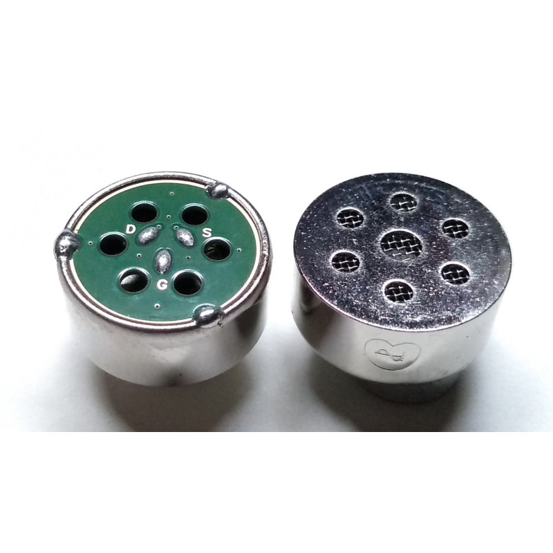
There are also three-terminal electret capsules, though not very common now. Those also bring out the source separately from the screen / electret element common which are the ground.

Edit - found an example:
 
Last edited:
The source in a two-wire capsule is also the ground connection; adding a resistor just increases the chance of noise pickup and reduces the output at the drain.

There are also three-terminal electret capsules, though not very common now. Those also bring out the source separately from the screen / electret element common which are the ground.

Edit - found an example:
much obliged
 
The Linkwitz modification is used for electret microphones used inside drums and pianos since it allows much higher sound levels before distortion. The Jfet is changed from a common source to a source follower. The output sensitivity is reduced. It is here:
 
Do these $2 capsules come in noise cancelling of figure-8 configurations? E
Cardioid or so-called unidirectional capsules tend to be somewhat more expensive, as they are less common and have a slightly more complex mechanical arrangement.

Example:
 
Another version, a three terminal with source as well as drain connections:
 
If the separate wires are long use a good decoupling capacitor across the power source at the point the microphone connections split. 100uF or larger, plus a 0.1uF in parallel.
 
ps. Don't use ceramic caps for coupling in audio circuits, they can introduce distortion.
they've been also known to be somewhat microphonic due to the piezoelectric effect in some ceramics. i've repaired guitar amps where somebody replaced some coupling caps with ceramic disc caps, and the disc caps would cause acoustic feedback.
 
Status
Not open for further replies.

Latest threads

New Articles From Microcontroller Tips

Back
Top