Continue to Site

Welcome to our site!

Electro Tech is an online community (with over 170,000 members) who enjoy talking about and building electronic circuits, projects and gadgets. To participate you need to register. Registration is free. Click here to register now.

  • Welcome to our site! Electro Tech is an online community (with over 170,000 members) who enjoy talking about and building electronic circuits, projects and gadgets. To participate you need to register. Registration is free. Click here to register now.

ECG device

Status
Not open for further replies.
Thanks! Okay. When you get the ECG signal recorded would you please post that? Please?

Most modern digital oscilloscopes provide a means to record the trace. I have seen this as a 3.5 floppy drive, and mostly now, USB for a thumb drive.
 
Last edited:
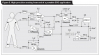
here is the final circuit..check it please and if you see something unproper tell me
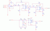
The new droopy passive lowpass filter is not a sharp active Butterworth Sallen and Key type.

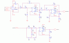
Your schematic has a grey background, is covered with dots, has big spaces which makes it huge and was saved as a very fuzzy JPG file type.
 
hi bro, do you know about and what's Noise Cancellation?
do you know how to make it?anybody have the circuits?cause really needed to remove the noise from our body, just i know our body is like antenna so our body receive all frequency arround us.i know this can mess up the signal of heart beat that i use to make ecg circuit.
if anybody know abut the niose cancellation for ecg circuit please share it with me.
tanx before
 
Two seconds ago I answered exactly this same question in your PM to me.

The common-mode signal (DC and mains pickup by the body) from the instrumentation amp is filtered and inverted then fed to the patient's right leg to cancel the common-mode signals.
 
so how i can make the common-mode cancellation opamp?
It was posted before. It takes the common-mode DC and low frequency AC from the instrumentation amp and feeds the patient's right leg like opamps A1 and A2 in this ECG circuit taken from the datasheet of an instrumentation amp:
 

Attachments

  • ECG circuit.PNG
    ECG circuit.PNG
    42.3 KB · Views: 1,278
how i can make the common-mode cancellation opamp in my circuit (see attachment)?
You are going around in circles.
Yesterday I posted an ECG circuit that shows an opamp making the common-mode cancellation signal. The circuit was posted twice in this thread.
Today I copied the ECG circuit from that datasheet of the AD620 intrumentation amp that you are using. It is here:

Don't you look at the datasheets of parts that you use?????
 

Attachments

  • ECG-3.PNG
    ECG-3.PNG
    22.8 KB · Views: 3,111
why my circuit still have a noise that is sinus signal so the heart beat signal cant be viewing? please help me to remove this noise?
tanx
 

Attachments

  • Circuit HBM.GIF
    Circuit HBM.GIF
    17.7 KB · Views: 885
As you have already been told, your simple circuit is missing the common-mode cancellation circuit that feeds the right leg of the patient instead of your ground wire.
The datasheet for the AD620 instrumentation amp shows it in their recommended ECG circuit.
 
i can't find AD705J so what i must to do to change it?
how i built th ehigh pass filter with frequency 0.03Hz?
then for the output amplifier use G= 143?
tanx
 
Last edited:
Simply look at the spec's of the AD705J opamp in its datasheet and find another similar opamp:
1) It has an extremely low input offset voltage and input offset current.
2) It has very low input current and a very high input impedance.

It is simple to make a highpass filter with a frequency of 0.03Hz.

It is simple to make an amplifier with a gain of 143.
 
Status
Not open for further replies.

Latest threads

New Articles From Microcontroller Tips

Back
Top