How can I trigger a device using a momentary tact switch already on another device?
I have a smart device that has a N/O momentary tact switch on its PCB.
I would like to use this switch to remotely trigger a remote bell.
The remote bell can be triggered using a momentary switch to connected to its trigger inputs.
When I soldered wires to the smart device tact switch and then connected those wires to the trigger inputs of the remote bell it is triggered as soon as both wires are connected... without the tact switch being pressed and closing the circuit.
The remote bell cannot be triggered again until a wire is disconnected and then reconnected to its trigger inputs.
It is acting as though the tact switch is closed even though it has not been depressed.
When I use my DMM across the SMD legs of the tact switch I get the following:
(The readings were obtained with the smart device disassembled and powered off. There is a button cell onboard to retain settings.)
continuity
open = 2.428
closed (pressed) = 0.002
resistance
open = 5.66 kOhm
closed (pressed) = 0.0 Ohm
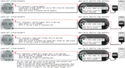
smart device tact switch

I have looked into simple mosfet and relay circuits to act as the middle man but I'm not really sure what would be the most reliable.
I have tested the smart device with a relay and it DOES NOT trigger the relay until the tact switch is pressed.
I don't think it would be a good idea to send any additional voltage through the smart device tact switch as I do not want to interfere with its original use or fry something in the smart device.
Is there a diode or something that I could add to the wires I connected to the smart device tact switch to prevent the remote doorbell from being triggered until the tact switch has been pressed?
Other details
The smart device has its own power supply (24VAC).
The remote bell has its own power supply (6VDC).
The devices are about 50 feet apart.
I did some further testing with a 12VDC power supply, a 12VDC mini SPST relay, and the smart device... I don't have the remote bell with me right now so I cannot fully test what I had been working on or what you recommend right now.
When I connect the smart device tact switch to the relay it does not trigger the relay until I press the tact switch.
After I release the smart device tact switch, the relay does not open.
Here is a diagram showing how I have it set up:

What route do you recommend I take?
Is there a way I can add a resistor and a capacitor (or something) that would draw down any voltage that is holding the relay closed?
Thank you all for your help!
I have a smart device that has a N/O momentary tact switch on its PCB.
I would like to use this switch to remotely trigger a remote bell.
The remote bell can be triggered using a momentary switch to connected to its trigger inputs.
When I soldered wires to the smart device tact switch and then connected those wires to the trigger inputs of the remote bell it is triggered as soon as both wires are connected... without the tact switch being pressed and closing the circuit.
The remote bell cannot be triggered again until a wire is disconnected and then reconnected to its trigger inputs.
It is acting as though the tact switch is closed even though it has not been depressed.
When I use my DMM across the SMD legs of the tact switch I get the following:
(The readings were obtained with the smart device disassembled and powered off. There is a button cell onboard to retain settings.)
continuity
open = 2.428
closed (pressed) = 0.002
resistance
open = 5.66 kOhm
closed (pressed) = 0.0 Ohm
smart device tact switch
I have looked into simple mosfet and relay circuits to act as the middle man but I'm not really sure what would be the most reliable.
I have tested the smart device with a relay and it DOES NOT trigger the relay until the tact switch is pressed.
I don't think it would be a good idea to send any additional voltage through the smart device tact switch as I do not want to interfere with its original use or fry something in the smart device.
Is there a diode or something that I could add to the wires I connected to the smart device tact switch to prevent the remote doorbell from being triggered until the tact switch has been pressed?
Other details
The smart device has its own power supply (24VAC).
The remote bell has its own power supply (6VDC).
The devices are about 50 feet apart.
I did some further testing with a 12VDC power supply, a 12VDC mini SPST relay, and the smart device... I don't have the remote bell with me right now so I cannot fully test what I had been working on or what you recommend right now.
When I connect the smart device tact switch to the relay it does not trigger the relay until I press the tact switch.
After I release the smart device tact switch, the relay does not open.
Here is a diagram showing how I have it set up:
What route do you recommend I take?
Is there a way I can add a resistor and a capacitor (or something) that would draw down any voltage that is holding the relay closed?
Thank you all for your help!
")