Zener_Diode
New Member
Hey.
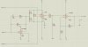
I am trying to do an ECG decive.
I am useing AD620 amp.
https://www.analog.com/UploadedFiles/Data_Sheets/37793330023930AD620_e.pdf
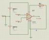
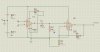
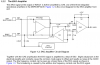
I built the circuit at page 12.
The leg I connected to the ground, and put 2.2K (or 100 om) between pins 1 and 8.
I am trying to see the ECG on scope. I don't see it, what I see is a straight line or 50Hz noise sin wave.
As electrodes I am useing a coins.
can some one help me plz?
I am trying to do an ECG decive.
I am useing AD620 amp.
https://www.analog.com/UploadedFiles/Data_Sheets/37793330023930AD620_e.pdf
I built the circuit at page 12.
The leg I connected to the ground, and put 2.2K (or 100 om) between pins 1 and 8.
I am trying to see the ECG on scope. I don't see it, what I see is a straight line or 50Hz noise sin wave.
As electrodes I am useing a coins.
can some one help me plz?