Continue to Site

Welcome to our site!

Electro Tech is an online community (with over 170,000 members) who enjoy talking about and building electronic circuits, projects and gadgets. To participate you need to register. Registration is free. Click here to register now.

  • Welcome to our site! Electro Tech is an online community (with over 170,000 members) who enjoy talking about and building electronic circuits, projects and gadgets. To participate you need to register. Registration is free. Click here to register now.

ECG device

Status
Not open for further replies.
Thanks a lot for the help..i will test the cct on monday and i hope is gonna work..i will upload my results on monday and hope to discuss again.

thanks
 
Okay, great. The learning is in the journey. If you hooked it all up and it worked the first time, there is not nearly as much to learn from that.;)
 
ECG Devise

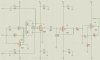
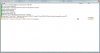
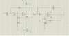
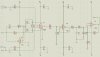
i have drawn the final cct using PROTEUS 7 professional software and when i run the simulation there are some errors that i cant find the solution..i attached the circuit and the simulation error if you know whats the problem please..

i set up the amplifier with G=7, after the right leg driver with G=1M/24.after the AD620 is a high pass filter Fc=0.03Hz with voltage follower G=1.after is the low pass filter Fc=100Hz and a non-inverting amplifier of G=144. so i have overall gain = 1008..but i cant understand why when i run the simulation it fails.

can you help me please
 

Attachments

  • ECG device 2.jpg
    ECG device 2.jpg
    191.8 KB · Views: 2,353
  • simulation.jpg
    simulation.jpg
    65.8 KB · Views: 896
when i draw the cct untill the high pass filter is simulating ok after when i connect the voltage follower and the non-inverting amplifier the simulation fails
 
Your simulation has the inputs floating. They should be connected to the right leg driver's output though a patient. Use 100k resistors.
The circuit also has no input. It needs to have an ungrounded differential signal between the two inputs.
 
when i draw the cct until the high pass filter is simulating ok after when i connect the voltage follower and the non-inverting amplifier the simulation fails

Include them one at a time to see whether it is the follower or the non-inverting amp. You changed two things at once. When troubleshooting, change one variable at a time. If the simulation fails only when the non-inverting amp is added, remove everything after the AD620 and try it again with the non-inverting amp in place. Simplify to narrow down the problem area.

As audioguru commented, you have no inputs and the output of the non-inverting amp is floating. That is not a valid simulation, since you won't be using the circuit that way. Also, without these, the initial conditions for the simulation as poorly defined. Judging from the time mark the error message gives for the error, it is failing right at the start. Simulate the human body too.

I am not a fan of simulators. They have their place, but they are fraught with pitfalls, especially in a situation like this with very high impedances. The node between R1 and R2 may not be accurately defined in the simulator's model for the AD620. That node is a non-conventional use for the AD620. Don't let the simulation results dissuade you from real experimentation in the lab.
 
Last edited:
thanks a lot for your comments.. Is there any problem when i put the hight pass filter first or after the low pass filter? i mean i must build the high pass flter and after the low pass filter or there is not any problem if is before or after?
 
on my cct i have the high pass filter first with voltage follower and after the low pass filter..if i change it and bring the low pass filter first with voltage follower and after the high pass filter with the non inverting amplifier it will change something?this is correct?
 
Your filters are so simple that they hardly do anything.
The lowpass filter should be the last one so that it reduces any noise from the highpass filter ahead of it.
 
The highpass filter is just a DC blocking capacitor. It is fine.
The lowpass filter should cutoff the harmonics of mains hum so a second-order or third-order filter will be better than the simple one you have now.
Texas Instruments recommends using a sharp cutoff digital lowpass filter that also cuts mains hum.
 
Can you please tell me the bandwidth of this bandpass filter? and the calculations if is possible please

what is the cut off frequecy of a low pass filter in an ECG device?
 

Attachments

  • bandpass filter 0.05-40Hz.jpg
    bandpass filter 0.05-40Hz.jpg
    156.2 KB · Views: 1,855
Your filters with the Chicken Pox dots are not correct. Look up Sallen and Key Butterworth filters in Google.
A Butterworth filter has damping so that the response is flat up to the cutoff frequency then a sharp drop. Your lowpass filter has a peaked response that is almost oscillating.

Your lowpass filter was set at 22kHz which is too high.

You don't need a second-order highpass filter. You just need a coupling capacitor that passes 0.03Hz and higher frequencies.
 

Attachments

  • ECG filters.PNG
    ECG filters.PNG
    36.1 KB · Views: 3,160
is there any software that i can download and connect my cct on the computer using a 3.5mm mono jack and record my ecg signal?
 
actually i got something good (i think at least)..))))) but i want to print it and i need a software that i can connect my cct on the computer and record the signal...do you know anything?
 
I don't know of one in particular. I found a freeware program some time ago that accepted input to a sound card and displayed it as an oscilloscope would. I can't remember the name or where I got it. A web search should reveal a slew of them. If it doesn't record the trace directly, you can do a print screen.

Edit: I looked, and the software that came with my Dell has a wavestudio recorder that will do almost as much. It doesn't display the signal in realtime, but it does record and then display it on playback. Maybe you have something like it.
 
Last edited:
i will searc the web thanks..as they told me there are digital and analogue oscilloscopes..i will see the ech signal on a analogue oscilloscope or i must use a digital one?
 
i will searc the web thanks..as they told me there are digital and analogue oscilloscopes..i will see the ech signal on a analogue oscilloscope or i must use a digital one?

Any app you will find will be an analog to digital conversion routine. So, I guess I would have to answer: digital. :rolleyes:

Can you post the circuit you ended up with?
 
i borrowed from a friend an oscilloscope but it desnt say if is digital or analogue.and when i was in the lab the oscilloscope that i was using it was digital.
anw here is the final circuit..check it please and if you see something unproper tell me
thanks
 

Attachments

  • pdsfpaidugyasdfuiasdfo.jpg
    pdsfpaidugyasdfuiasdfo.jpg
    191.6 KB · Views: 1,164
Status
Not open for further replies.

New Articles From Microcontroller Tips

Back
Top