Continue to Site

Welcome to our site!

Electro Tech is an online community (with over 170,000 members) who enjoy talking about and building electronic circuits, projects and gadgets. To participate you need to register. Registration is free. Click here to register now.

  • Welcome to our site! Electro Tech is an online community (with over 170,000 members) who enjoy talking about and building electronic circuits, projects and gadgets. To participate you need to register. Registration is free. Click here to register now.

ECG device

Status
Not open for further replies.
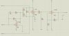
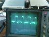
I have attached a schematic diagram of ECG device that i builded. it is based on ECG device given from AD620 instrumentation amplifier datasheet..i ve tested the first part of the circuit (AD620 and AD706 right leg driver)using oscilloscope but the signal i was getting it was not a proper one.when i attached the RA and LL electrodes i could see a signal looking like an ecg but not a proper one but when i was connecting the RL (ground) the signal disapeared.can anybody tell me why? now i have builded the whole circuit with a high pass filter after the AD620 of cut off frequency 0.025Hz and an operational ampliier of G=143.does the circuit looks ok or shall i make some changes? shall i include a resistor at the non inverting input of the last op-amp for input impedance?
 

Attachments

  • ECG.jpg
    ECG.jpg
    163.4 KB · Views: 2,231
If you do not use the proper parts then it probably will not work.
 
The circut is the same as on the datasheet of AD620 instrumentation amplifier but i included the high pass filter and the operational amplifier at the end..as i have made it now you think that it will not work?
 
For the right leg driver i am thinking to use AD706JNZ instead of AD705J that the datasheet says because is little difficult to find a AD705J..AND for the last amplification stage i am thinking to se AD548KNZ or AD8031ANZ operational amplifiers..can you please tell me in your opinion which is the best to you for each case?
 
try to increase the constant time of R3 and C1 from 1mS to a few seconds. This driving lag circuit should cancel vary of body potencial. I guss it is cancelling your ECG result. Also try to connect your RL to graund without driving leg circuit. tell me what are the results.

good luck
 
Your probes are on only one arm but both legs.
The heart is between the arms so two of the probes should be on the arms.
 
Your probes are on only one arm but both legs.
The heart is between the arms so two of the probes should be on the arms.

Actually the highest amplitude differenetial ECG signal is from the right arm to the left leg, referenced to the right leg....the standard clinical ECG "Lead II" configuration.

The attached is from the Tektronix 1976 Peter Strong "Biophysical Measurements" text book. From my early days in Medical Electronic.

Ken
 

Attachments

  • ECG Leads.jpg
    ECG Leads.jpg
    59 KB · Views: 1,529
Actually the highest amplitude differential ECG signal is from the right arm to the left leg, referenced to the right leg....the standard clinical ECG "Lead II" configuration.
Then why did Analog Devices and Texas Instruments show it wrong?

Recently I had an ECG and there were 10 probes.
 
I can use the combination between the leads but for better results Lead ii is best i think.RA,LL and RL(GND).Last night i was searching if there is an op-amp for the right leg driver that can replace the AD705J because i cant find in any electronic strore here.anybody have an idea for alternative op-amp?
 
the basic circuit that i am working on is the ECG circuit that i found in AD620 datasheet..instead of AD705j i used AD706 but i think is not the proper one..i have attached the full ecg schematic that i builded so can you check it please and let me know if everything is ok with it?and what kind of op-amp i can use at the final amplification stage with G=143?i need an 0p-amp that i can connect it as non-inverting ampliier.
 
I can use the combination between the leads but for better results Lead ii is best i think.RA,LL and RL(GND).Last night i was searching if there is an op-amp for the right leg driver that can replace the AD705J because i cant find in any electronic strore here.anybody have an idea for alternative op-amp?
What's wrong with using the AD706?
 
i have tested the output using the AD620 and the AD706 as a right leg driver and here is the output that i got. i didnt include in this stage the high pass filter and the last amplier with G=143 yet.the output is from the AD620 with the right leg driver..
 

Attachments

  • GetAttachment.jpg
    GetAttachment.jpg
    31.4 KB · Views: 801
i have tested the output using the AD620 and the AD706 as a right leg driver and here is the output that i got. i didnt include in this stage the high pass filter and the last amplier with G=143 yet.the output is from the AD620 with the right leg driver..
Changing the op amp is not going to make an appreciable difference.
What is the frequency and amplitude of that waveform? Are you getting it from a human body?
 
yes this signal i got it from me..i had the electrodes placed on me but to get thi signal the Right leg was connected on ground and not in the output of the AD706..i didnt measure the frequency and amplitude of the waveform because the time i got this signal the lab that i was in was closing and i had to go..so on monday i will measure it and let you know.but it was the best signal i could get from the oscilloscope that one.what do you beleive the problem might be? is anything to do with resistor R3 and capacitor C1 as i ve drawn the circuit? or do you believe if i include and the high pass filter Fc=0.03Hz and the op-amp with G=143 i will get a proper ecg signal?
 
Then why did Analog Devices and Texas Instruments show it wrong?

They didn't show it wrong, just different. Right arm/left arm is just convenient, and will get a "Lead I" signal.

Recently I had an ECG and there were 10 probes.

The other 6 electrodes are referrer to as "V Leads". Attached. Though the diagram shows a "C" in the middle of the chest, it is one of the six (switchable) "V" electrodes.

Ken
 

Attachments

  • ECG Leads 1.jpg
    ECG Leads 1.jpg
    56.7 KB · Views: 759
Last edited:
What operational amplifier shall i use to set it as a non-inverting amplifier in order to amplify the final signal G=143?LM741 op-amp is not efficient op-amp so what other types of op-amp do you recomend? what about AD548KNZ or AD8031ANZ?
 
yes this signal i got it from me..i had the electrodes placed on me but to get thi signal the Right leg was connected on ground and not in the output of the AD706..i didnt measure the frequency and amplitude of the waveform because the time i got this signal the lab that i was in was closing and i had to go..so on monday i will measure it and let you know.but it was the best signal i could get from the oscilloscope that one.what do you beleive the problem might be? is anything to do with resistor R3 and capacitor C1 as i ve drawn the circuit? or do you believe if i include and the high pass filter Fc=0.03Hz and the op-amp with G=143 i will get a proper ecg signal?
The main purpose of the feedback op amp is to cancel the common mode noise that your body picks up - mostly mains frequency and harmonics thereof. If grounding the body were sufficient, ECG circuits would not use the common-mode feedback op amp. I suspect you will find that the frequency you are seeing is mains, or a harmonic. If not, then your circuit may be oscillating.
 
So Roff do you recomend me to cancell out the feedback op amp and just connect the AD620 with a high pass filter and a non-inverting amplifier with G=143? because if i connect the right leg with the output of the feedback op amp the signal dissapears and i get a straight line. for lead cables i am using coaxial cables, in the one end i solder the inner core with crocodile clips and i attach it on the electrode and at the other end of the cable the inner core i connect it with the input of the AD620 and the metallic shield of the cable to the ground.is that correct?
 
What are you using for electrodes? It's bad enough that the signal is minuscule save without a good connection to the skin.
 
Status
Not open for further replies.

Latest threads

New Articles From Microcontroller Tips

Back
Top