Continue to Site

Welcome to our site!

Electro Tech is an online community (with over 170,000 members) who enjoy talking about and building electronic circuits, projects and gadgets. To participate you need to register. Registration is free. Click here to register now.

  • Welcome to our site! Electro Tech is an online community (with over 170,000 members) who enjoy talking about and building electronic circuits, projects and gadgets. To participate you need to register. Registration is free. Click here to register now.

Duty cycle detection

Status
Not open for further replies.

earckens

Member
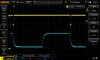
I need to detect a duty cycle going past a certain threshold. Here is a picture of the duty cycle in yellow; as this decreases from the current approx. 95% to say 50% (adjustable), it needs to trigger an output (TTL level). Preferably with some upper threshold too.

What is the best way to approach this?

Edit: the amplitude of the signal to be detected is constant amplitude TTL level (so, yellow trace at TTL level).
 

Attachments

  • DS1Z_QuickPrint11.jpg
    DS1Z_QuickPrint11.jpg
    75.9 KB · Views: 153
Last edited:
I would like to be able to set the on-trigger at about 50% with +/-5% accuracy, and the off- trigger at about 30% with same accuracy.

Edit: the frequency remains fixed at about 2kHz; amplitudes always are TTL level.
 
I would stick a capacitor on the input side & stuff it into an Arduino's A/D, where you can set the thresholds to your heart's content
 
I would stick a capacitor on the input side & stuff it into an Arduino's A/D, where you can set the thresholds to your heart's content
That is a software solution. I prefer hardware because it makes the module I want to make independent of any software.

Ultimately I will use the output of the hardware solution in a microcontroller, but not at this stage.
 
The easy way is to use an RC filter to get the average voltage and then use a comparator to detect the level.

You can also use a microcontroller.

How accurate do you need it?
Preferably not a microcontroller; anyone with a solution using a 555 and/or comparator?
 
anyone with a solution using a 555 and/or comparator?
A 555 can any job! I am using one as a door stop.

How fast do you want the circuit to respond? The "RC" circuit will take several cycles to respond. I can make one that will respond in one cycle.
 
Input is the green trace. (V2) To the left it was 100%. Then went to a low % and then after 14 cycles went back to 100%.
The blue trace is after the RC. It averages the 0V and 5V to get a level.
Output is in red.
Right now it is set to trip at 33% and 66%. That can be changed.
Not right but something to think about.
upload_2017-10-11_16-43-41.png

I do not like using the RC filter method from "TTL". Because TTL does not pull up well. You should buffer the signal with a CMOS buffer so the pull up is good and predictable. CD40xx or 74Cxx
 
Another approach is for the leading edge of the signal to trigger a fixed monostable circuit that times out at the 50% point. The trailing edge of the signal clocks a flipflop. The monostable output is the D input to the ff. If the signal is less than 50% DC, its trailing edge clocks a 1 into the FF, signalling a fault condition. If the signal is greater than 50% DC, it clocks a 0 into the ff because the monostable has timed out. There is a bit more to it, but that is the basic approach.

The benefit of this approach is cycle-to-cycle monitoring without the delay of a lowpass filter.

ak
 
A 555 can any job! I am using one as a door stop.

How fast do you want the circuit to respond? The "RC" circuit will take several cycles to respond. I can make one that will respond in one cycle.
Funny :).
Speed is no requirement at all; This system has a step response of an hour!
 
I do not like using the RC filter method from "TTL". Because TTL does not pull up well. You should buffer the signal with a CMOS buffer so the pull up is good and predictable. CD40xx or 74Cxx
Right, I agree. Can you maybe include this where needed in your schematic please?

And what components on the 555 are "in charge" of the 33% and 66% triggers?
 
Another approach is for the leading edge of the signal to trigger a fixed monostable circuit that times out at the 50% point. The trailing edge of the signal clocks a flipflop. The monostable output is the D input to the ff. If the signal is less than 50% DC, its trailing edge clocks a 1 into the FF, signalling a fault condition. If the signal is greater than 50% DC, it clocks a 0 into the ff because the monostable has timed out. There is a bit more to it, but that is the basic approach.

The benefit of this approach is cycle-to-cycle monitoring without the delay of a lowpass filter.

ak
Thank you for that input! Very usefull too. Do you maybe have a schematic handy for this idea?
 
Can you maybe include this where needed in your schematic please
Put the CMOS gate/buffer just ahead of the RC. So the TTL signal probably is 0V and 4V the CMOS buffer 0V/5V.
555 are "in charge" of the 33% and 66% triggers?
I tied 2 and 6 together and injected the RC signal there.
The 1/3 and 2/3 voltage points are set by the three resistors from 8 to 1. I don't remember but I think the resistors are 10k. ????
Connect a 1k from 8 to 5 and the "TRIG" voltage will be just below 50% and "THERS" will be about 95%.
***I need to look at the data sheet to see if the inputs will work that close to VCC.***
upload_2017-10-11_17-26-26.png

Another option is to add some resistors to 6 and some to 2 to shift the voltage up or down.
 
Put the CMOS gate/buffer just ahead of the RC. So the TTL signal probably is 0V and 4V the CMOS buffer 0V/5V.

I tied 2 and 6 together and injected the RC signal there.
The 1/3 and 2/3 voltage points are set by the three resistors from 8 to 1. I don't remember but I think the resistors are 10k. ????
Connect a 1k from 8 to 5 and the "TRIG" voltage will be just below 50% and "THERS" will be about 95%.
***I need to look at the data sheet to see if the inputs will work that close to VCC.***
View attachment 108565
Another option is to add some resistors to 6 and some to 2 to shift the voltage up or down.
Hi Ronsimpson, what are "2 and 6", and "from 8 to 1" and "from 8 to 5"?

I just downloaded Splice, I wonder why I have not used that before :cool:

Edit: oh I see, are these the 555 pins?
 
It appears the "top" input THRES will work to VCC. The bottom input TRIG will work all the way down to GND.
upload_2017-10-11_17-38-1.png

I do not like this circuit but I took up the challenge.
 
It appears the "top" input THRES will work to VCC. The bottom input TRIG will work all the way down to GND.
View attachment 108566
I do not like this circuit but I took up the challenge.
It appears the "top" input THRES will work to VCC. The bottom input TRIG will work all the way down to GND.
View attachment 108566
I do not like this circuit but I took up the challenge.
Why do you not like it?
Please feel free to propose an alternative?
Thks!
 
I started out using a "74ls122" and some logic. [analogkid #9] Set one timer for min time and the other timer for max time.
Too many ICs but will give you a results in one cycle. (time dependent not duty cycle dependent)

Next I did a analog design that is just like a 555 with out the three resistors. Two pots sets the two voltage levels. If I could get at the three resistors and force the levels to 50% and x% with a POT or two, then I would feel better.
(duty cycle dependent)
Could use a dual CMOS 555 and use 1/2 as a buffer.
 
Just for fun I added a 1K from pin5 to pin8. Switches at 92% and 46%.
Maybe the resistor should be closer to 820 or 750.
upload_2017-10-11_20-44-38.png
 
Status
Not open for further replies.

Latest threads

New Articles From Microcontroller Tips

Back
Top