Continue to Site

Welcome to our site!

Electro Tech is an online community (with over 170,000 members) who enjoy talking about and building electronic circuits, projects and gadgets. To participate you need to register. Registration is free. Click here to register now.

  • Welcome to our site! Electro Tech is an online community (with over 170,000 members) who enjoy talking about and building electronic circuits, projects and gadgets. To participate you need to register. Registration is free. Click here to register now.

Blown fuse detection parallel battery bank

Mrusten

New Member
I can not wrap my head around circuit designing, it's highly annoying!
Could please someone help me to design the circuit I'm looking for?
And please I'm looking for a circuit not other solutions like microcontroller LED across fuse, etc.

So my issue:
I have 6 leaf modules in parallel 8.4v when fully charged. That means that each cell is 4.2 V and I want to fuse each cell, the center pin is connected in parallel across all 6 modules that means I need a circuit for the negative terminal sensing and a circuit for the positive terminal sensing. It's a part of a large bank so the currents is max 25 A for each module (each fuse is 25 A).

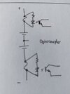
I already found part of what I'm looking for here from this post.
but i think a voltage difference sensing circuit could work as well.
the circuit should also latch the outputs for the led and transistors just to make sure there is no intermitted faults passing by, and a reset switch to reset the latching

I have 384 fuses and 32 banks of 6 modules so that's why I'm looking for a circuit I can use for each of the parallel banks and wire it up to the Siemens PLC, no addressing required as the LED will show what fuse is blown.

0aiPj.jpg
 
Dear friend,

Just use a optocoupler to detect the fuse blown.
We have some possibilities about utilizing the output transistor of the coupler.

Regards
 

Attachments

  • WhatsApp Image 2023-10-12 at 10.10.46 AM.jpeg
    WhatsApp Image 2023-10-12 at 10.10.46 AM.jpeg
    65.4 KB · Views: 97
You don't even need the opto coupler if you have visibility of the fuses. Just put a 220 ohm resistor in series with a red LED and clip it across the fuse.

Or, use fuses with an integrated blown LED like this (this one is a non-name brand that I've seen at auto stores...
Yes, a LED in series with a resistor is enough for visible indicator.
An opto coupler will be useful if we "connect" them to controller for remote monitoring.

Anyway, now our friend has more option for the solution he needs.

Warm Regards.
 
I'd have to say a Hall sensor would be the best option.

 
A fuse will blow when the the flowing current is greater than its rated value. When the battery is full charge, the current almost zero, so no fuse will blow. The biggest current will flow for the first time charging after it supplies the load. That is the critical state that the fuse may blow. So, our detector will still work.
 
I'd have to say a Hall sensor would be the best option.

Hall censor utilizes low ohm-ic shunt resistor. The purpose of a fuse is to protect from excessive currents. In my opinion, Hall censor will not protect the batteries.
 
Hall censor utilizes low ohm-ic shunt resistor. The purpose of a fuse is to protect from excessive currents. In my opinion, Hall censor will not protect the batteries.
You may be confused...
"The Hall Effect current sensor is used where non contact current sensing over a wide input operating ranges with responsiveness to very high frequency inputs are critical design criteria. A Hall Effect sensor is particularly suited to measuring DC current and DC current pulses."
 
The physically simplest method is to use "Striker" fuses and matching holders:
eg.

Striker fuses have a spring loaded pin that is released when the fuse blows. That makes it totally independent of current or voltage measurements, it's either good or indicating blown.

The holders take a microswitch (that's operated by the pin) giving a fully isolated indicating circuit.
See page five of this datasheet for an example holder that can have a microswitch added:
 
thanks for all the answers but a led need to high voltage difference to light up,
here is testingresults of one of my batteries, voltage ranging from 8,2v to 7,25v in my case my goal is to use 60% of the avalible energy in the battery so i wil probably try to use the batteries between 8,1v and 7,5v that means cellvoltages between 4,05v and 3,75v thats only 0,3v voltage difference between fully discharged and fully charged.
i also do not think there is enough currentflow for the led to light as there is 6 high capacity batteries in paralell and im having low loads

i would not like to be limited by a led to light if a fuse blow so a circuit to detect the fuse state is needed

sodapdf-converted.jpg
 
I think that the striker fuses are a good idea. I have seen them used on three-phase circuits, so that when one fuse blows, the circuit is turned off, to protect the other two phases.

When one fuse blows, the current will be shared with fewer fuses, so they will take more current and it is quite possible that all the fuses will blow, so the usefulness of a circuit that detects a single fuse blown is not clear.

You could use an amplifier of some sort so that a small voltage difference across a blown fuse could be amplified to run an LED.

Another approach would be to have current transducers on all the fuses, and if one went to zero when the others were working, you would know that a fuse had blown. However, if you go to the expense of current transducers, the signals from them could directly shut down the circuits without needing to blow a fuse at all.
 

Latest threads

New Articles From Microcontroller Tips

Back
Top