Continue to Site

Welcome to our site!

Electro Tech is an online community (with over 170,000 members) who enjoy talking about and building electronic circuits, projects and gadgets. To participate you need to register. Registration is free. Click here to register now.

  • Welcome to our site! Electro Tech is an online community (with over 170,000 members) who enjoy talking about and building electronic circuits, projects and gadgets. To participate you need to register. Registration is free. Click here to register now.

Dust extractor remote switch

Status
Not open for further replies.

HDC83

New Member
Hi everyone
I have a dust extractor that has power take off to turn on when I switch a tool on. I also fitted a rf remote switch to turn the extractor on/off for cordless tools but I have to switch it over from auto to manual which is a bit off a pain as extractor is tucked away and usually has table saw in front off it.
So that leads me to ask if anyone knows how to fool the extractor to think there’s a tool in the power take of that’s on a remote the festool one. (I can get it to work using remote switch and plugging in an old drill but not ideal really) I would really like something that has trailing leads plug and socket so I plug this in line with my other tools or even something small enough to go inside the extractor somewhere.
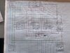
I have another idea I that I would need someone to check over if it would work(pic below) same as above apart from not using the auto start on the extractor. Just putting it all in 1 box together.
Thanks for taking the to read and hopefully someone will understand me lol

Curt
 

Attachments

  • EB96BE92-44E3-47ED-8B80-243218298657.jpeg
    EB96BE92-44E3-47ED-8B80-243218298657.jpeg
    4.7 MB · Views: 257
I don;t exactly know what I'm looking at.

Hints:

But you can fool the "system" by paralleling a contact across the current sensor switch output.

usually, you need a delay on break relay to keep the system alive until another device comes online. it also vacuums out residual dust. In general, you put a current sensor at each device or a voltage device. By voltage device, a relay that just provides a contact to the dust collector.

Portable tools, use a cord reel or your remote.

An additional problem that crops up, is for larger devices, like a table saw you might want to use your remote to turn on the extractor and then the saw the first time, so the saw and extractor don;t com on at the same time or you can add a short delay, e.g. turn on saw. A few seconds later turn on the dust extractor.

You also might have to open/close dampers,
 
Hi I will try to explain the drawing
I would like to have my corded tool ie mitre saw/router table/table saw plugged in all the time and when I use one off them I would like the extractor to switch on and have a 10 second off delay that’s why I was thinking of 12v sensing switch to the 12v timer delay relay to switch ssr for the extractor to switch on. I also use cordless tools and would like to turn on the extractor and have the same 10 second off delay via a remote. So put 12v remote relay using diode but not sure if I would need one.
 
You might be missing a delay. That would be that once the last device turns off, start a timer for a few minutes that keeps the extractor on until another device draws current.
 
You should be able to just put the switches in parallel. I doubt if the diodes are needed. I've got a garage light that turns on when the PIR sensor notices movement in the garage, or the light is on, or when the garage door opener has operated in the last minute. That is just three switches wired in parallel.

I don't see why the remote switch that you added needed to have some change-over device. It could have just been put in parallel with the current sensor in the dust extractor. Maybe if you explained how that modification to the dust extractor was done it might help.
 
This is to be independent to the extractor, I want it to control the power cord going to the extractor. The change over device is ac to dc transformer as the relays and switches are 12v dc.
 
I come up with the same thing Diver300 said. Your current sensor(s) is just a switch that eventually turns on the dust extractor through a high current relay/SSR. Any device just needs to parallel that. It could be individual equipment or or a remote.

That contact needs to be extended say a minute, so your not turning the extractor on and off.

You may not want the saw and dust extractor to turn on at the same time.

Usually, the equipment could be all over the shop and there might be a circuit panel that feeds each piece in a lrgae shop.

You "can" put current sensors in that panel.

You don;t have to use current sensors either, Just a relay after the power switch that detects the power is turned on

A cord reel is a great way of handing smaller devices.

The remote for stuff you didn't think of.

24VDC is common for process control, not 12.
The only glitch that can really complicate this, is if it's necessary to open/close damper doors for the machines.

Any piece of equipment, would have to open a damper door when it;s turned on.

The final thing is to have a damper that opens to control the static pressure.

That's the ultimate system when you take into account everything it needs to do.

Make sense?

Remember that in most of the current sensors you can increase sensitivity by using multiple turns,

Wiring needs to be limited to 100 W and <24V without conduit.
 
I thought the current switch and remote switch need separate feeds as I want them to work at different times. Cause my understanding is the remote switch wouldn’t pass the signal from the current switch through without in switch on?

(That contact needs to be extended say a minute, so your not turning the extractor on and off) Sorry not sure on what you mean I’m only a wood butcher lol

My work shop is only 6mx3m and only have portable tools not large machines. It’s set up in away to be able load in my van to use for site work. At the moment I have a daisy chain with powercon connectors where the tools get set up and then plugged into small dust extractor which works a treat tbh.
Only have 40mm pipe and home made dampers at arms reach from each tool.
I would love to have the ultimate setup you suggest if I had a bigger workshop
 
So that leads me to ask if anyone knows how to fool the extractor to think there’s a tool in the power take of

Going back to post #1, All you really need is a load. back in the "old days" switching on a lamp would work.

Resistors, are not cheap, but it depends on the minimum current plus a safety margin. e.g. https://www.digikey.com/en/products/detail/vishay-sfernice/LPS0600H4700JB/2233866

that's 470 ohm 600 W.

I=240/470 or > 0.51 Amps ; Guessing 240 V mains

P= V*V/R; so > 122W; You'll need some margin of safety, 600W is too much.

I don;t know the numbers, so I won't waste time optimizing a solution.

So, your remote switches on a resistor, "load" that allows the extractor to turn-on.
 
Thats exactly what I want here’s a picture of the spec of sander it’s the smallest wattage tool I have to check that turns on the extractor. I just knew you would come up with something that would work for me.
 

Attachments

  • 9BC8019F-E6A3-4001-AAEB-3A1A8DAF5F43.jpeg
    9BC8019F-E6A3-4001-AAEB-3A1A8DAF5F43.jpeg
    1.1 MB · Views: 233
I didn;t see post #9 until now.

(That contact needs to be extended say a minute, so your not turning the extractor on and off) Sorry not sure on what you mean I’m only a wood butcher lol

What this means is:

Say I'm using a belt sander that turns on the dust collector. I turn off the belt sander because I want to use the finishing sander.
The dust collection system, should not go off at the same time I turn off the belt sander. It should give me some time, to put it down and turn on the next tool. order of magnitude (minutes). If I don;t pick up another tool in x minutes, the dust collector turns off.

So, pretty much you have one current sensor like your diagram indicates.

You have two choices:

#1: "bypass" the current sensor with the remote.
#2, Add a load to fake it.

#1 is your best option.

I "think" you missed the usual design goal of not stopping/starting the dust collection system. In real shops, it's huge.
This is the job of the retrigerable "delay on break" timer. It pretends the tool is on for a short time (1 minute) after the tool turs off.

You don;t have to worry about the tool and the dust collector turning on at the same time.

it "might" be worthwhile, not essential, to have an indicator that you are remotely triggered especially if you use "toggle the state".

When you have "no idea" what the important specifications are, you have nowhere to start. I picked the ultimate "dust collection" system. You can always whittle down from the ultimate design.

1. A dust collection system need to do (the following).
2. I need it to do (this).
3. In the future, I anticipate (this).

Build for #3, but include the parts for #2. it saves grief in the future.

Sometimes, I miss. Usually, I don't. Sometimes I have to give in. then someone else takes the blame. It was their decision.

Examples:

I wanted no "cards" in a computer. That was the right answer. I was told to use cards.

I messed up controlling 6 mass flow controllers because of ground references and computer control. Everything else worked out.

Then you have a nano cost-concious manager that doesn't like the UPS I specified. it's not well known that generators may interfere with the way UPSs operate. I needed one compatible with a generator. It needed to provide power for up to 2 minutes until the generator kicked in. The system was "critical".
 
NO!

P=(V^2)/R; 240*240/22
That's 2618 Watts.. I=240/22 is around 10 Amps.

If you want to use 170W; P=(V^2)/R --> PR = V^2 --> R <= (V*V)/P ; R<= 240*240/170 --? R<=338 ohms.
Probably 200 mA of current would work (just a guess).
R=240/.2 = 1200 ohms. How about 1K. P = 57.6 Watts, so the rating of the resistor has to be higher, say 1.5 to 2x,so 100 W is probably fine.

One thing to keep in mind is that if the units are VA, you can probably use that number. If Watts, maybe not.

--

Why even go that route, Just parallel a contact across your current sensor contact, which I assune is a sensor that closes it's switch above a certain current.
 
See something like : https://www.geya.net/timer-relay/multifunction-time-relay-2/ E. Off delay.
So, you need to create a set of potential free contects from your current sensor (relay). This guy gets powered all of the time. The contacts, of the relay go in parallel with your current sensor switch(s). This, then keeps the contact energized for say 1 minute after turning something off. Also known as a delay-on-break timer. Aliexpress has these really cheap usually.

They mount on TS32 DIN rail which provides the basis of a control engineer's erector set.

I'll use this https://www.asi-ez.com/ website as an example of what's available. RS has DIN stuff too.
 
NO!

P=(V^2)/R; 240*240/22
That's 2618 Watts.. I=240/22 is around 10 Amps.

If you want to use 170W; P=(V^2)/R --> PR = V^2 --> R <= (V*V)/P ; R<= 240*240/170 --? R<=338 ohms.
Probably 200 mA of current would work (just a guess).
R=240/.2 = 1200 ohms. How about 1K. P = 57.6 Watts, so the rating of the resistor has to be higher, say 1.5 to 2x,so 100 W is probably fine.

One thing to keep in mind is that if the units are VA, you can probably use that number. If Watts, maybe not.
--

Why even go that route, Just parallel a contact across your current sensor contact, which I assune is a sensor that closes it's switch above a certain current.

Are talking about the current sensor inside the extractor?

Does it make a difference that the voltage/p is 110v to the calculations sorry don’t think I’ve mentioned that before. Hi All my tools and extractor are 110v.

Thanks for all you advise
 
yea, it does. I saw a reference in the thread to the uk. This is times where the general area helps.

All of the numbers change,

So, the "block diagram" that I saw a while back is not yours. I did the calculations for 240 which was my guess.
Of course it matters.

110V puts it in some wierd country,

I got the impression that you built the device that turns on the extractor. Now, I see your reluctance in modifying that device,.

Here, https://www.conservationmart.com/p-317-bits-smart-strip-7-outlet-scg-3mvr.aspx is such a strip. it takes a 15W minimum load to be sensed. A 5W florescent load can be sensed and this makes sense. An inductive load like a motor draws a spike of current briefly at start-up


So, that's an ersatz "poor substitution for the real thing" dust collector switch. If that's the case, i wish I knew that earlier.

it doesn;t have the wierd nonsense of staying on briefly.

15W is a whole lot less current. P=VI l says 15=120*I; I=0.125 Amps. that's on the order of what I suggested. Why i picked that, it's about a minimum load size for a triac to stay on.

The other 1 minute timer is still a possibility.

Something should be in the specifications for what the load can be,

You have power, voltage, current and resistance. You need two of the 3 to find the other on

the two basic equations are:

P=V*I and V=I*R; with those two equations, you can solve for what you need.

The delay on break timer would just be powered all the time much like the remote receiver. You would have a 120V coil relay to create an isolated contact closure for your delay on break timer. the contacts of that timer would be in parallel with the contacts of your remote switch.

Only thing I can think of is the the voltage and contact ratings of the remote receiver.
 
Totally understand wish I mentioned that Im from the uk but jobsite tools are 110v here via a step down transformer.

the remote switch that I have been using is

So if I use the voltage at 110v and resistance at 50 ohm I get 242 watt and 2.2 amp so if I use this one would work?
 
Sorry about all the confusion
This is the spec of the extractor it’s actually 115v for some reason we say it’s 110v
 

Attachments

  • EC0ACA6D-4924-42C4-9194-465F1F779E97.png
    EC0ACA6D-4924-42C4-9194-465F1F779E97.png
    279.2 KB · Views: 232
I've heard that before. People in the uk likes 120V power tools.
I have good and bad news:

Your cutting it too close on wattage. This https://uk.rs-online.com/web/p/panel-mount-fixed-resistors/6641871/ might be a better choice. A 400W resistor was cheaper than a 300 W resistor. You don't have to solder if you use the wire leads.

250w is a lot of power to be wasteing, but it's actually good news too.

The RF switch is sold as a "Definate purpose contactor", so if you were switching 0.1 Amps, the relay contacts MIGHT become unreliable
A relay has what;s called a "Wetting current". That's how much current you have to minimally have for good reliability.
250W has a really good chance of not exceeding that.

I don;t LIKE the design, but it should work.

A note:

2 resistors of the same value in parrallel is: Req=R/2 so, two 8 ohms is equal to 4.
Wattages add: so Two 100W 8 ohms in parallel is 200W at 4 ohms,

Resistors might be found at surplus places,

250W is too close to 242. I'd be happier with a 300W. resistor.

i was thinking you were using smething like this https://www.amazon.com/eMylo-Wirele...nsmitter/dp/B01A6VO79M/ref=asc_df_B01A6VO79M/

But note,, no real info on the relay contact ratings.
 
Status
Not open for further replies.

Latest threads

New Articles From Microcontroller Tips

Back
Top