RAR2k
New Member
I have just started testing a pre-soldered kit from Aliexpress bought with its clear enclosure for around 18€ including shipping.
At first I was utterly disappointed from
1) no instructions on how to assemble the enclosure. I could have guessed, but come on... then I found something online.
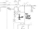
2) there was an offset (even in GND switched mode) of about 0.86V that I could not figure out how to clear. Online I did not easily find anything related to this issue on this model.
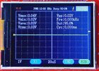
3) Probe calibration on the 1V setting was not possible as the edges of the square wave were still too rounded.
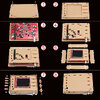
EASY SOLUTIONS
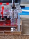
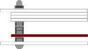
1) See image
2) click SEL several times until the left cursor that indicates your zero is selected, then old down OK! Voilà!
3) Replace C5 (1pF) with a higher value. 2pF was good for me. I added a 1pF in parallel on the bottom side of the PCB - now I can adjust C6 for the correct shape.
I will continue to test this gadget and see to what extend it can be used - I don't expect too much, but it might be helpful for minor projects.
At first I was utterly disappointed from
1) no instructions on how to assemble the enclosure. I could have guessed, but come on... then I found something online.
2) there was an offset (even in GND switched mode) of about 0.86V that I could not figure out how to clear. Online I did not easily find anything related to this issue on this model.
3) Probe calibration on the 1V setting was not possible as the edges of the square wave were still too rounded.
EASY SOLUTIONS
1) See image
2) click SEL several times until the left cursor that indicates your zero is selected, then old down OK! Voilà!
3) Replace C5 (1pF) with a higher value. 2pF was good for me. I added a 1pF in parallel on the bottom side of the PCB - now I can adjust C6 for the correct shape.
I will continue to test this gadget and see to what extend it can be used - I don't expect too much, but it might be helpful for minor projects.