Continue to Site

Welcome to our site!

Electro Tech is an online community (with over 170,000 members) who enjoy talking about and building electronic circuits, projects and gadgets. To participate you need to register. Registration is free. Click here to register now.

  • Welcome to our site! Electro Tech is an online community (with over 170,000 members) who enjoy talking about and building electronic circuits, projects and gadgets. To participate you need to register. Registration is free. Click here to register now.

Detecting DC voltage threshold and firing a relay or switch (Automotive)

danny_b

New Member
Hi everyone. I am junior level electronics hobbyist and I'm hoping to get some help designing some kind of voltage switch for an automotive application.

Precisely what I am trying to do
Detect if the DC voltage on a circuit is above or below a certain threshold (say 1.0V) with reasonable accuracy and toggle a switch or relay if the condition is met WITHOUT influencing the voltage on the circuit.

Background
  • I'm installing automotive gauges that measure engine oil pressure
  • In order to do this, I've had to remove the factory oil pressure switch that goes into the engine block and replace it with an AEM oil pressure sensor that outputs a 0-5V signal corresponding to oil pressure
  • Whilst this works great for the new gauge, the removal of the OEM oil pressure switch means the "low pressure" red light in the vehicle dash is permanently OFF.
  • The OEM oil pressure switch has a single wire that pulls to ground on the engine block when pressure is low.
  • As this sensor is now removed and unplugged, the dash light is permanently off.
  • What I'm trying to do is simulate the output of the factory OEM pressure switch using the signal from the new and improved oil pressure sensor I have installed.
  • i.e. If the output from the new sensor is below 1.0V (indicating low oil pressure) I need to physically connect the now disconnected OEM sensor harness plug in the engine bay to GND, presumably via a relay or switch.
The problem I'm trying to solve
Emulate the output from an OEM oil pressure switch using a new generation oil pressure sensor in a simple, low cost, reliable and elegant way.

Why go to all this effort?
  • I have already explored using Tpieces (to dual mount sensors) and other spare oil gallery port locations in the engine bay, but there is no viable alternative to have both sensors mounted at the same time (i.e. I have to ditch the OEM switch)
  • I've already designed and built a custom harness to run the gauges and new pressure sensor, this is the final piece that would make it perfect and give an OEM feel.
What avenues have I explored
  1. Voltage switch with Zener diodes and similar. I've done some research into diodes and it seems like these could be a cool way to have an electrical switch. I'm not sure if this would be an appropriate pathway to try as they look like they would influence the base circuit Im trying to measure. i.e. I don't want to disrupt the signal voltage from the sensor to the gauge, but somehow measure it and do something.
Diagram Attached
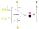
I've attached a simple schematic showing what I'm trying to achieve. I don't want to use anything like an Arduino, Rhaspberry Pi or any advanced circuitry, but I'm happy to build a breadboard and solder a bunch of components if someone can help me design a viable circuit.

Thanks all


Dan
Screenshot 2023-05-03 at 8.00.17 PM.png
 
Last edited:
An opamp, used as a comparator, with a onchip Vref would allow you to do it in 1 chip.

LM10 or LT1635


This OpAmp looks like :

1683107021840.png


So you use 2 R's to amp the 200 mV reference to 1V,
and apply that to the OpAmp. The OpAmp also has
2 R';s to give it some hysteresis.


Page 20, Voltage Level Indicators, shows possible circuits, flashes as well.

You should protect the LM10 from "load dump", using a TVS :


Regards, Dana.
 
Last edited:
Thanks Dana, I am 70% understanding so far. I'm close. I've been diving into opamps and comparators (both concepts new to me) and I'm wondering if a simple comparator could do the trick also?

Something like
  • supply the comparator with GND and 5V
  • set the threshold input voltage from feeding back 5V supply down to 1V with resistors
  • feed in the sensor signal output voltage into Vref
  • Then this should produce a digital 5V or 0V output based on where the Vref sits.
  • I could then use this to presumably drive a relay that connects a separate line to complete the OEM sensor circuit that would fire the dash light to come on or off in the right conditions.
Would something like this also work or am I crazy?
Could then tweak it with hysteresis stuff if needed (Schmitt trigger)
Screenshot 2023-05-03 at 11.35.07 PM.png
 

Attachments

  • Screenshot 2023-05-04 at 12.00.59 AM.png
    Screenshot 2023-05-04 at 12.00.59 AM.png
    96.6 KB · Views: 139
Last edited:
Yes but your circuit has issues.

You use 12V auto supply and a divider to generate the Vref, but 12V varies significantly, eg
it makes for a poor Vref. Range of "normal" auto V is 11 - 15 volts. Thats roughly a 50%
error in your Vref implmentation.

The LM10, LT1635, the OpAmp can be used as a comparator, and it has onchip the Vref as well.

How much current do you need relay to switch ?

I do not see any hysteresis implemented on Comparator, like the simed LM10 shows ....?

Dont forget to use a TVS solution on the circuit power supply. And place a .1uF ceramic disk
in parallel with a 10 uF or so cap on circuit power pin. Close to OpAmp/Comparator power
pins.


Regards, Dana.
 
Last edited:
Here's another circuit using the common TL431, 2.5V shunt reference, and LM339 or LM393 comparator:
It uses a power N-MOSFET to connect the dash lamp (red trace current) to ground when the sensor (green trace) is below 1V.
R3 provides about 100mV of hysteresis.

The circuit can be easily modified to be powered by 5V, if that's preferable.

1683133897892.png
 
Last edited:
Thanks all, this has been super helpful to put me on the right track. Basically I'm in opamp and comparator territory and it sounds like I just need to experiment with some circuits to get it doing what I want.

Regarding the supply voltage, FYI I have a 5V regulated circuit on my harness which uses an LM7805. This produces a stable 5V regardless of input voltage 12-14V from main Engine (alternator) so I think this solves the vref issue and might help me keep the circuit super simple.

It seems like most comparators and opamps are like 2.5V or 5V input anyway, so this all sounds promising. So appreciative of the circuit diagrams. I will report back on progress.
 
Aren't you guys over engineering this? An idiot light only comes on at no oil pressure. It's not a pressure gauge only an on and off switch.
 
Aren't you guys over engineering this? An idiot light only comes on at no oil pressure. It's not a pressure gauge only an on and off switch.
Good point.
The TS said he wanted the light to come on at about 1V, but that voltage is likely not critical and shouldn't need the accuracy of a comparator.

Below is the sim of a two transistor circuit that turns the lamp on when the sensor voltage drops below about 1V.
Adjusting the value of R3 will vary that if needed, with a minimum of about 0.7V as the value of R3 approaches infinity (R3 removed).

C1 and R4 protect Q1 and the gate of M1 from transients.

1683221123414.png
 
Last edited:
The TS said he wanted the light to come on at about 1V, but that voltage is likely not critical and shouldn't need the accuracy of a comparator

Couldn't it be done with a Pmos? the original light is powered from the ignition switch and the sender grounds when there is no oil pressure. So when the new circuit is sending a signal to the gauge the gate dould be fed by that signal. When the signal is gone(no oil pressure) the Pmos would then turn on and ground the light circuit, and light comes on. Unless I'm wrong about how a Pmos works.
 
Unless I'm wrong about how a Pmos works.
You are.
The new sender signal is 0V-5V, but a P-MOSFET requires the gate to be essentially at the source (battery) voltage to turn-off, so no. a single P-MOSFET won't work.
 
Why use a comparator ? Noise. No hysteresis..... Although we could think
of it as a feature, LED starts to dim.......:) No really large cap needed on a
comparator as its PSRR serves us well in rejecting 12V bus noise. Not perfect,
still recommend a TVS for load dump issues.

1683240049060.png


And then of course we have not considered accuracy. Is the sensor poor in this respect, that adding
the inaccuracy of a Vbe approach as Vref on top of that cause led to not come on as engine oil
pressure so low its imminent failure. Why design this way when only pennies are involved ?

Regards, Dana.
 
Last edited:
Below is the comparator circuit modified to work from 5V.
Since the 5V supply should be reasonably stable I eliminated the voltage reference and used the 5V to generate the 1V threshold reference.

1683251172127.png
 
Last edited:
You are.
The new sender signal is 0V-5V, but a P-MOSFET requires the gate to be essentially at the source (battery) voltage to turn-off, so no. a single P-MOSFET won't work.

I thought they had logic level Pmos too. I'm just an old but rank amateur at this electronics thing.
 
I thought they had logic level Pmos too. I'm just an old but rank amateur at this electronics thing.
Yes, but that has nothing top do with this application.
You need to consider how a P-MOSFET is connected to switch a plus voltage, since it needs a negative gate-source voltage to turn on.
That means the MOSFET source must be connected to the plus voltage, and then grounding the gate will provide the required negative bias to turn on the MOSFET as a high-side switch.
And to turn if off, the gate voltage must be raised to the plus (source) voltage.
Make sense?
 
Last edited:
A P-MOSFET curve showing the drain current vs. the gate-source voltage for a fixed Vds:
The MOSFET turns off when the Vgs drops below the V(gs) threshold of about -1V.

1683307856568.png
 

New Articles From Microcontroller Tips

Back
Top