Continue to Site

Welcome to our site!

Electro Tech is an online community (with over 170,000 members) who enjoy talking about and building electronic circuits, projects and gadgets. To participate you need to register. Registration is free. Click here to register now.

  • Welcome to our site! Electro Tech is an online community (with over 170,000 members) who enjoy talking about and building electronic circuits, projects and gadgets. To participate you need to register. Registration is free. Click here to register now.

Dissapointed from a LED light bulb...

Status
Not open for further replies.
To clarify... each 5050SMD LED contains three emitters in parallel inside it (by guessed data sheet).
There is 51 in series, fed from the full-rectified mains. There is two equal circuits for a total of 102 LEDs in the bulb.
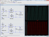
The picture shows the two joined PC boards, each driving a series of 51 LEDs.
The hand-drawn schematic shows only one of the 2 circuits fed by mains.

Eliminating the 'driver' circuit can promote the thermal runaway as Vf decreases, but seems more risky the effect of spikes on mains.
It is a cheap chinese bulb with no true current regulation, but '30 Watts' will make my kitchen really bright as wanted instead of the 200 Watt incandescent. The rest of the house rooms use the 9W ones from the Lowe's link.

Edited + Added another 1.5uF to the 1.5uF series capacitor for 3 uF total, Zc=884 Ohms, If = 0.0177 A. No smoke.
Voltage drop is now 15.7V across C. Means raised 5V to the series of 51, measured Vf being 2.9V.
Will evaluate brightness at night time, and perhaps increase capacitance again before doing a direct connection to mains.
 
Last edited:
Having had 40 yrs of R&D, TestEng & Mfg then retired to LED biz, I would ignore this design , ie scrap it and go forward with DC power distribution in the house and low cost matrix power chips.

For AC bulbs it must have PFC above 30W and should be dimmable SMPS design, such as Honeywell, Philips etc.


The FW bridge cap divider to LED design is far too sensitive to line voltage, variation which may be 120 in your area and less than rated power or ~125~127 as in my area near Toronto. All mainstream consumer bulbs now use SMPS and not this simple method. It works well for DC but poorly for AC.

Other Reasons: Pulsed duty cycle results in higher loss efficacy. Also no-name brand Chinese factories unless specs given will use off-spec or low efficacy cheaper bins of CREE parts.

I have successfully modeled all diodes for Vf vs I with a linear approximation using ESR and a threshold voltage near 10% of rated current. This works well for simulation confirmed with lab tests and datasheets with expected tolerances for ESR, whereas threshold voltage is fixed for each chemistry.

Never assume all white LEDs are 3.3Vf, 5050 LEDs have lower Vf from lower ESR with higher power rating.

For these diodes, white SMD I choose 2.8V depending on pulse mode rather than DC.
e.g. SSC-STW8T16C 5050 are typical of this style ( picked as cheapest at Digikey )
315mW max with suitable heatsink
Vf 2.8~3.3 , 8.2Cd Warm White

The ESR * Watt Rating product (for all diodes ) ranges from 0.5 for the best and ~1 for nominal designs.
For this class of LED Pd= 315mW and my Rule of Thumb , Pd(rated) *ESR = 1 nom. depending on several variables.

upload_2016-1-1_16-33-2.png


The best way I see of salvaging this design with some line tolerance is to add ~=100 Ohm PTC's (Polyfuse) to supply more pulsed current. Doubling C also works at the risk of more line sensitivity.

upload_2016-1-1_16-45-11.png
 
Last edited:
Here is 1.5uF, 3.0uF, 4.5uF and 6uF.
Red is HV capacitor voltage.
Blue is LED voltage.
Green is LED current.
upload_2016-1-1_14-55-19.png
 
I agree Ron but the voltage drop across rising values of C to < 10% of the line voltage and thus prone to flicker with line or load variation in the home such as electric heaters turning on, whereas a 100 Ohm or 0.1A Polyfuse or thereabouts would also boot current and adjust with slow line changes. In the end it is a poor design for low cost.
 
We all agree this is a bad idea.
Here is a try at varying the line voltage.
Green trace is LED current.
Voltage is peak not rms! 140V, 150v, 160V, 170V, 180V
150pk = 106, 160pk=113 rms, 170=120 rms, 180V=127
upload_2016-1-1_16-3-17.png
 
Thanks guys. Yes, a poor design.
Night time now. Tried the bulb with 3uF series capacitance. Better, but still dissapointed, smells that can do much better. I will raise the 4.7uF/400V DC filtering/smoothing capacitor value now, to increase the turn-on time of the LEDs during the AC cycle.

Tony : Implementing a PTC would allow to cope with 127-130VAC; but does nothing for spikes protection, right ? Will see which transzorbs values reside in my bins.
 
Glad we are all on the same page.
Actually I think his hunch that this was 240V only for 30W is correct.

I est. close to 20W avg (-72Wp) with 240Vac 339Vp
upload_2016-1-1_18-49-19.png
 
Tony : Implementing a PTC would allow to cope with 127-130VAC; but does nothing for spikes protection, right ? Will see which transorbs values reside in my bins.
Yes I agree with that.
The LED's act as high power zeners with current limiting by series impedance at risk of exceeding ratings, but then no big loss ;)
 
I have dozens of PAR20 50W Halogen ceiling lights which I am gradually replacing with 5W PAR20 indoor floods from Phillips.

Dimmable instant on 35 deg beam.
330 lumens soft white (5000K)

Looks identical to Halogen lights except reflected colours are only very slightly greenish, but incident light looks the same.

This demonstrates the balanced RGB still is not full spectrum lower level deep red wavelengths in White LED's
upload_2016-1-1_19-0-36.png


For my purpose the midrange CCT is ideal for me.

My ideal house is all central DC powered LEDs with local dimmers running off 48V in basement.
But around yard I use a laptop universal charger to drive strings of 5
or 12V to run strings of 4 with Rs=0

upload_2016-1-1_19-6-20.png


The down side of 5W PAR20 lights with 330 lumens is that equates to 66 Lumens per Watt while my 4ft FL tubes are 88 Lumens /Watt are actually better. So until I get 160 Lumens/Watt parts from Toshiba, I'm can't agree all LEDs are better than 4ft efficient 30 or 32W tubes, but possibly smaller ones.

CRI, CCT ['K] and LPW (lumens per watt) and cost are all critical factors often not advertised.
 
Last edited:
You might also jump around 11 of them with the 3 Ufd. and see how that looks. :wideyed:
 
or if possible rewire them to strings of 24S 4P instead of 51S 2P

The danger of high peak/average current is exceeding the chip spec often limited by small margins.
eg. absolute max 100mA rated power 65mA
 
You might also jump around 11 of them with the 3 Ufd. and see how that looks.
3uF is right for 120Vac and 25 LEDs.
---edit---
The bulb at 120 as made for 220 is almost worthless with some mA of current.
It looks like you could rewire for 1/2 as many LEDs and double the capacitor. That will make 1/2 the LEDs bright.
---edit again---
I have talked many times about not paralleling LEDs. BUT;
Change the cap to 6.8uF and have two strings of 25 LEDs each. (parallel 25+25)
The LED boards can be rewired with the white wires.
 
Last edited:
3uF is right for 120Vac and 25 LEDs.
---edit---
The bulb at 120 as made for 220 is almost worthless with some mA of current.
It looks like you could rewire for 1/2 as many LEDs and double the capacitor. That will make 1/2 the LEDs bright.
*@# forgot to save it.
Well, if they are E's LEDS at 3.8 Vf it's probably to many. He is already at Tony's 2.9, so I left it at 3.3. :D
I think at 25 the current is over 50 ma.
 
One more time.
 

Attachments

  • e led.png
    e led.png
    130.2 KB · Views: 159
  • e's leds.asc
    4 KB · Views: 136
Reporting :
- As bought with 1.5uF mains series capacitor and 4.7uF smoothing capacitor = disappointing.
- 3uF mains series capacitor instead of 1.5uF and a 4.7uF smoothing capacitor = a bit better but nowhere near expectations.
- 3uf mains series capacitor and 33uF smoothing capacitor = nothing better discernible; a nice 3 second fading turning off.
- 'Driver circuit disemboweled, the two series of 51 LEDs counterparalleled directly to 120VAC mains = no smoke, still disappointing, with slight flickering noticeable by the corner of eyes.

Am back to incandescent in the kitchen, until some other day test for smoke making it series of 25 LEDS. The packing box is labeled 110VAC 30 W, the vendor advertised as 85-265V mains.

Total = another chinese garbage.
Yes, I think you are a victim. :(
It might be worth noting they are about 25 watts peak, but only about 8 watts average. I think that makes it about like a 60 watt bulb.
You might try it with the cap jumped but still keep the bridge.
 
You might try it with the cap jumped but still keep the bridge.
Then what will limit the current? That is like putting a "3V LED" on a 3.3V DC supply with out a resistor. Something that we see done all the time by hobbyists.
 
Hi.
Bought this 30Watt

----> **broken link removed**

with 102 leds, supposed to be for 85 to 265 VAC; gives less light than a 15Watt fluorescent CFL.
Supposed to have cree brand leds, but they do not tell the type/model in order to measure/test if the bulb is correctly built/labeled/driven.

Two equal circuits inside are each a 1.5uF/250V capacitor in series with a full wave rectifier to 4.7uF/400V electrolytic filter capacitor feeding series of 51 LEDs, no limiting resistor.

1.5uF at 60 Hertz result in Zc = 1768 Ohms.

A series of 51 white LEDs assumed at 3.3 Vf result in 168 Vf

120V AC after the bridge rectifier and filter are supposed to yield 170V DC

Measured Vf of one LED, shows 2.82V when bulb is lit;
AC supply measured 120.4V;
Capacitor drop measured 20.4V AC.
20.4VAC in 1768 Ohms = 0.011 A
So there is 100VAC / 141.4 V peak into 51 LEDs, resulting in 2.77Vf for each.

Seems LEDs are underdriven.
Do I raise the series capacitor to 2.0 uF for Zc = 1326 Ohm ? Or more ?

Or, eliminate the mains bridge rectifier/capacitor/filter and connect the two sections of 51 series LEDs in counterparallel to mains ?

Or, short circuit a few LEDs to raise Vf and If ?

Or, could the bulb be mislabeled as for 120V and it is intended for 240V ?

Or, what would you do ?


Schematic----> https://s588.photobucket.com/user/Innernet/media/P1010590_zpsn1ztzgxb.jpg.html?sort=3&o=0

Hi Externet,

Yes, your LED string would be struggling with 120V RMS (170V peak) at 60Hz.

There are two aspects to the design:

(1) the amount of energy transfered during each half cycle of the input sine wave; this is dictated mainly by the value of the input capacitor C5.

(2) the voltage of the transfered DC energy stored in the second capacitor, C4; this is defined by the ratio C5/C4 and the current drain from C4.

Try connecting the points circled in purple on the schematic below: that should fix the problem, although it may be necessary to adjust the value of C5 to get the brightness that you want.

To test put a 220 Ohm resistor in series with the LED string just to play safe.

Be interested to know how it goes.

spec

PS: The four rctifier dides shown on the schematic have no special significance: they are only there because I was too lazy to get a bridge symbol from the parts library.


Capture.PNG
 
Last edited:
Thanks, guys.
Then what will limit the current? That is like putting a "3V LED" on a 3.3V DC supply with out a resistor. Something that we see done all the time by hobbyists.

There is no need to limit the current if Vf is kept within safe LED specifications. Try connecting a 3.3V LED rated to a 3.3V supply; it may run forever with no problem as 3.3V is a rating within specs and will draw only its corresponding current for its V-I curve.

Spec: Perhaps you missed reading 'reporting' that the last attempt was :

Driver circuit disemboweled, the two series of 51 LEDs counterparalleled directly to 120VAC mains = no smoke, still disappointing, with slight flickering noticeable by the corner of eyes.

I had better successes with nothing else than a capacitor in series making these counterparalleled 'night lights' from discarded CFL housings and other junk :
----> https://s588.photobucket.com/user/Innernet/media/P1010435_zps200dcafc.jpg.html?sort=3&o=28
 
Status
Not open for further replies.

Latest threads

Back
Top