Continue to Site

Welcome to our site!

Electro Tech is an online community (with over 170,000 members) who enjoy talking about and building electronic circuits, projects and gadgets. To participate you need to register. Registration is free. Click here to register now.

  • Welcome to our site! Electro Tech is an online community (with over 170,000 members) who enjoy talking about and building electronic circuits, projects and gadgets. To participate you need to register. Registration is free. Click here to register now.

Diode-less Power MOSFETS

Status
Not open for further replies.
i must have done something wrong , what did you get??
Edit Duhh, i forgot the real Fets ,,
but i like the look of it..
 
Here's the circuit with the comparators...

If you want to simulate it, let me know if you have problems. I could post waveforms, but it would be much more instructive to do it yourself and see what happens when you change the load resistance, filter cap, generator source resistance, etc.
 

Attachments

  • sync_rect_sch1.gif
    sync_rect_sch1.gif
    7.6 KB · Views: 777
Ron H said:
Try replacing the upper transistors with p-channels, as below.
ok i did that , but it doesnt seem to work as well as mine.
i may have made a mistake , but yours seems to fall apart after a load battery of 10V..while mine keeps pumping current into a battery of 17V..!!
 
williB said:
Ron H said:
Try replacing the upper transistors with p-channels, as below.
ok i did that , but it doesnt seem to work as well as mine.
i may have made a mistake , but yours seems to fall apart after a load battery of 10V..while mine keeps pumping current into a battery of 17V..!!
You're right. I had only tested it with a resistive load. When you put a filter cap on it, or a battery, it falls apart.
 
Ok i constructed the auto Rectifier..
One side works a lot better than the other..
since i didnt have 8 Mosfets of the same type on hand i had to mix n match..
That may have been the problem..
the one side gives me 624 mA , with the other sides gates not connected

so this is pretty promossing because that is 624 mA half wave rectified current (measured)..
if i post the scope output maybe someone out there can see a problem..
 
This is the output from the simulator..
i've lowered the " source" to 12V which seems more like what i was actually getting under load conditions..
pretty sweet huh ?
 

Attachments

  • rectifier.jpg
    rectifier.jpg
    75.4 KB · Views: 690
  • virect.jpg
    virect.jpg
    39.1 KB · Views: 691
Ron i tried running your rectifier ( with comparators) but with the sim program , grounding right next to the Sources produces strange results..
also i tied the op amps power and noninverting input ahead of the Mosfets which seemed to produce better results..
 
williB said:
This is the output from the simulator..
i've lowered the " source" to 12V which seems more like what i was actually getting under load conditions..
pretty sweet huh ?
Pretty sweet...
Take a look at this comparison.
 

Attachments

  • sync_rectifiers_waves.gif
    sync_rectifiers_waves.gif
    11.6 KB · Views: 635
  • sync_rectifiers_sch.gif
    sync_rectifiers_sch.gif
    9.1 KB · Views: 678
williB said:
Ron i tried running your rectifier ( with comparators) but with the sim program , grounding right next to the Sources produces strange results..
also i tied the op amps power and noninverting input ahead of the Mosfets which seemed to produce better results..
For some unknown reason, I thought (until recently) that you were trying to drive a resistive load, i.e., to convert generator AC to a DC voltage that would drive a load. I finally realized that you are charging a battery - with no current limiting except the generator resistance. :shock:

I didn't try the comparator/Pchan rectifier as a battery charger. It sim'ed really well as a FW rectifier into an RC load, as shown.
 
That one with the P-channel Mosfets works great !!
i wonder why that is ?


I finally realized that you are charging a battery - with no current limiting except the generator resistance.
of course..
 
I think you're still misunderstanding the point here.

A resistive load does not store power. The problem is that ANY mosfet implementation- be it a NMOS, PMOS, or a bizzare combination of them- allows current to flow either direction when vgs is greater than the threshold voltage.

So you may be trying to charge a 12v battery or cap with a 12v AC motor, which means 17v peak. OK, so the battery charges for the portion of the signal where Vmotor>12v. But what happens when the AC signal swings back towards zero? As soon as it goes below 12v, the battery or cap will discharge its power back into the power source. A diode will not do this. I see one of the schematics included a blocking diode after the rectifier. Nice but this will drop 0.7v which is half the problem we wanted to avoid in the first place.

The ideal diode is realized by putting an amp on Vds, when it is in the desired direction we turn on the gate. Some forward threshold is still essential since if Vds is driven to 0 then the circuit will either turn itself off when it should be on, or if there's a positive offset error, may never turn off even when the current goes the wrong direction.

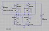
The PMOS can be switched by simply looking if the source is + or -, but then NMOS must be switched by looking at the direction current will flow. Then the NMOS don't have much risk of turning on at the same time, though the PMOS do. Or you could build the fullwave rectifier as before and make the "ideal diode" on the output, then you only have to build 1 but it's an extra transistor. It will bring back the problem of the NMOS turning on at the same time though.
 
Oznog said:
As soon as it goes below 12v, the battery or cap will discharge its power back into the power source.
you would think so, but i have not seen this on the scope or the simulation..although i found a pecularity which you should take a look at..
instead of using a battery i used a 2.2F cap , with a bunch of smaller caps to absorb some of the power and pump it back into the supercap..
The blue is the current in the 2.2F cap..
The light green is the voltage across the load(caps and supercap)..
The sim was done for 2.4 sec. at which time the voltage on the load levels out to about 3.6 V ..why 3.6V and not some other voltage??
Also the current starts to go negetive as the caps reach their final voltage..why??

the source is ( 0 , 12, 100 ) w/1.3 ohms internal resistance...
 

Attachments

  • 2.4ssch.jpg
    2.4ssch.jpg
    43.7 KB · Views: 620
  • 2.4sec.jpg
    2.4sec.jpg
    62.5 KB · Views: 633
williB said:
you would think so, but i have not seen this on the scope or the simulation..although i found a pecularity which you should take a look at..
I think that's what your sim is saying.
williB said:
at which time the voltage on the load levels out to about 3.6 V ..why 3.6V and not some other voltage??
I think that's because the source is draining the cap charge back to the motor, as previously described. 3.6V is probably from the threshold voltage of the mosfets. When the source voltage is above this, it's connecting the source so it conducts current the wrong way for part of the cycle.

williB said:
Also the current starts to go negetive as the caps reach their final voltage..why??
Same problem. Your driving strategy is flawed. Fix it!

And you're using 2 mosfets where one will do the job- still don't know why you want to do this, it does not help you.
 
ok i've added a single diode to prevent that from happenning ..
the way i look at it a single diode drop is only half as bad as as two diode drops per leg..
the new sim looks much better , i'll post it when its done..
the reason i'm using two mosfets is the single diode approach just doesnt work
 
ok this looks much better..
i have added a single diode at the output to the load..
voltage is in blue current is in green..
 

Attachments

  • rectwdiode.jpg
    rectwdiode.jpg
    50.5 KB · Views: 778
ya know , when you put a relatively low voltage battery(fixed voltage) in the load the current never goes negetive either..
with or without the diode..
 
williB said:
the reason i'm using two mosfets is the single diode approach just doesnt work
I think that's because, again, you're driving it incorrectly.
 
Status
Not open for further replies.

Latest threads

Back
Top